Method and apparatus for measuring capillary pressure and foam transport in porous media

a technology of capillary pressure and foam transport, which is applied in the direction of instruments, nuclear magnetic resonance analysis, and wellbore/well accessories, etc., can solve the problems of inability to measure the capillary pressure before, unsuitable or inaccurate simulating transient foam flow, and inability to accurately simulate the foam trapping process. , to achieve the effect of high resolution

Active Publication Date: 2020-08-06
KING FAHD UNIVERSITY OF PETROLEUM AND MINERALS
View PDF0 Cites 16 Cited by
  • Summary
  • Abstract
  • Description
  • Claims
  • Application Information

AI Technical Summary

Problems solved by technology

Foam models and parameters are often derived from laboratory coreflood data determined at a steady state foam flow regime, which makes them unsuitable or inaccurate for simulating transient foam flow.
Since significant foam trapping occurs in the transient flow regime, foam trapping processes are not adequately covered by existing models.
However, it was not possible to measure the capillary pressures before steady state foam flow (or before Pc*).
None of these methods could be conducted directly in a consolidated porous medium.
However, it was not possible to obtain separate measurements for injected and corresponding trapped gas at each stepwise change in water saturation nor was it possible to measure foam flow behavior in porous media.
In addition, it cannot be used to characterize the flow behavior of the foam in the porous medium.
However, the method uses a porous medium simulator, not a single coreflood experiment in combination with capillary pressure and other measured data points to characterize foam transport in porous media.

Method used

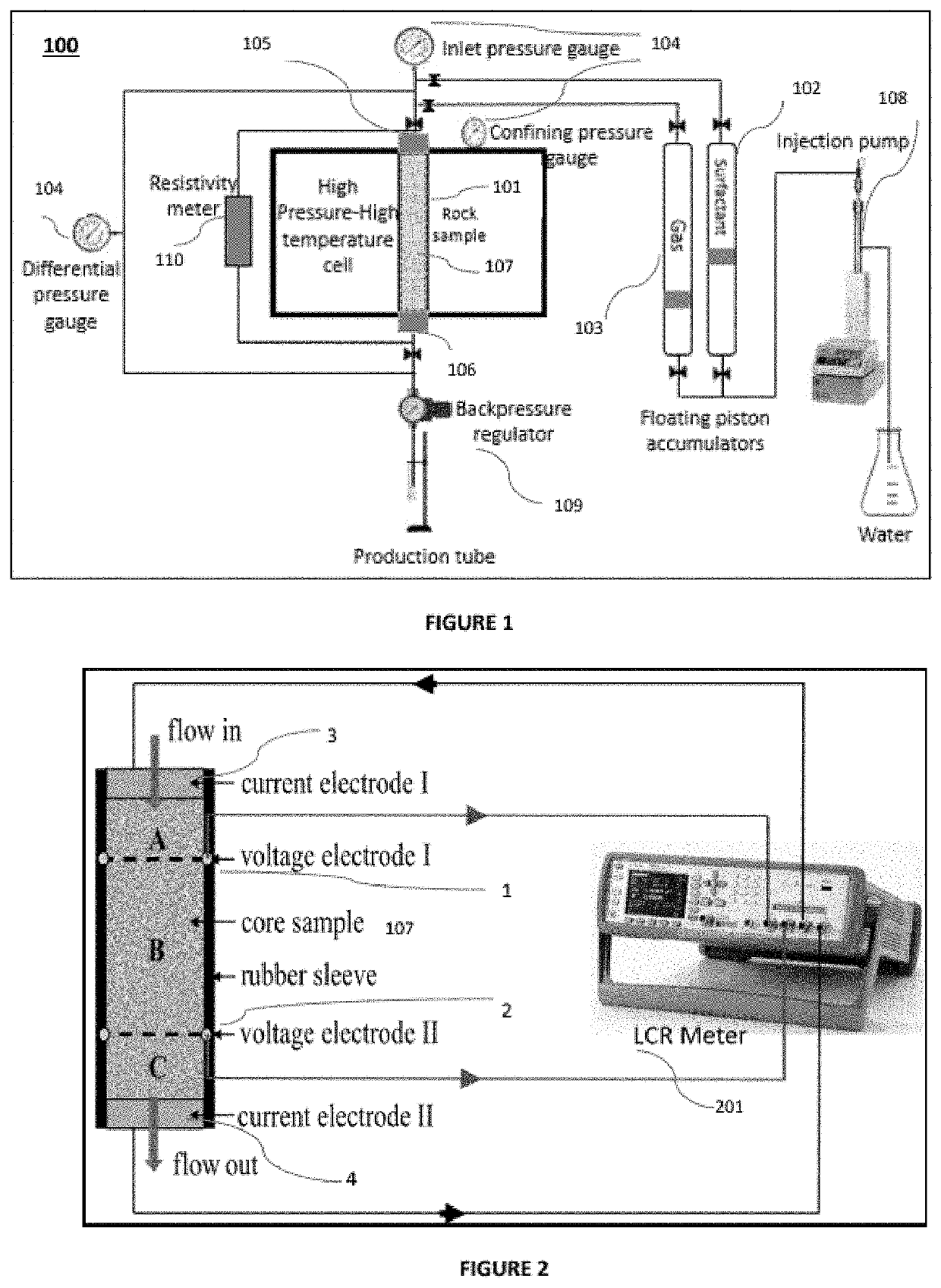
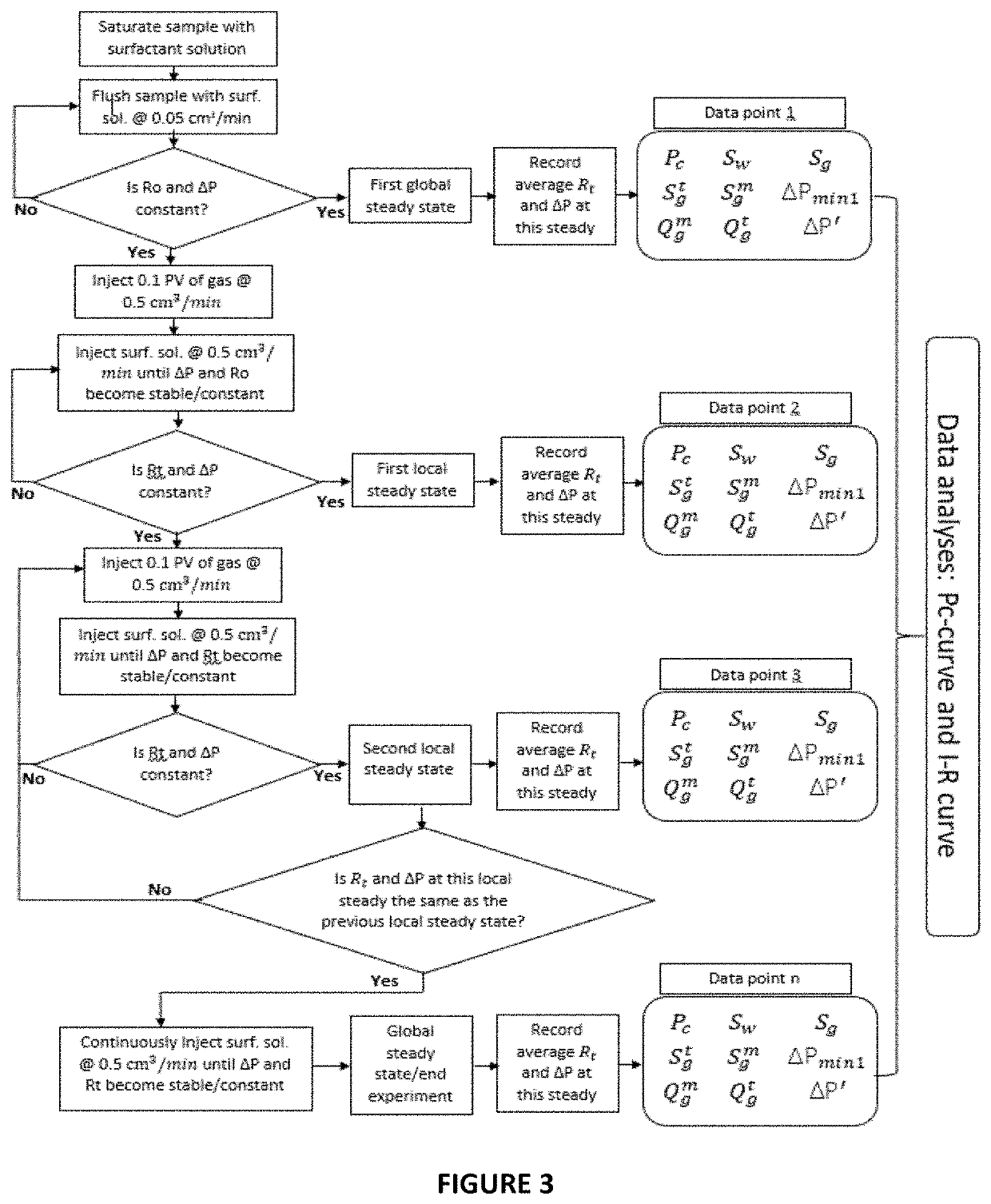
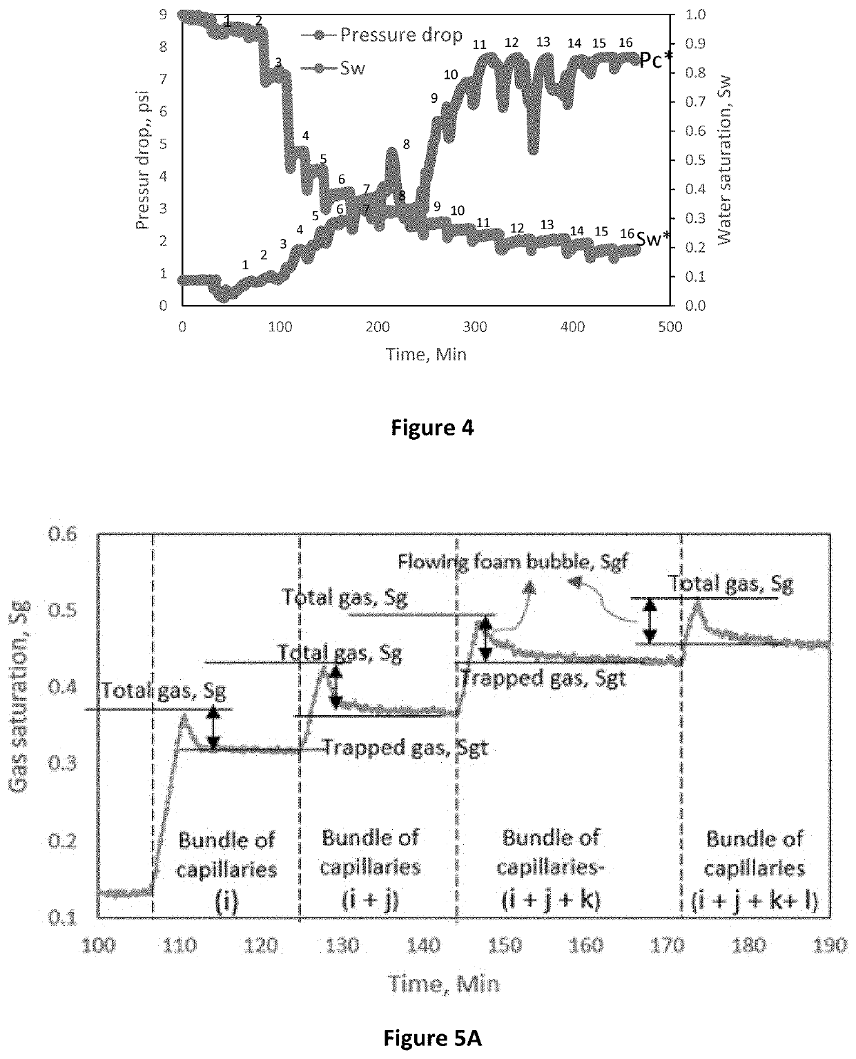

Image

  • Method and apparatus for measuring capillary pressure and foam transport in porous media
  • Method and apparatus for measuring capillary pressure and foam transport in porous media
  • Method and apparatus for measuring capillary pressure and foam transport in porous media

Examples


example

[0058]A test sample of cylindrical rock (10.6 cm long and 3.76 cm in diameter) was extracted from an Indiana limestone outcrop (with porosity of 15% and brine permeability of 5mD). The sample was cleaned by flushing with methanol in a Soxhlet apparatus at 80 ° C. for three days in order to remove any salt deposits that may be in its pores. It was then dried in a vacuum oven for 24 hours in order to dry and evacuate the pores. The sample was then saturated with a brine solution containing dissolved surfactant. Saturation was conducted by vacuum method after which the sample porosity and pore volume were estimated based on the difference of it's dry and saturated weights. Synthetic brine solution of 58,000 ppm was formulated in the lab using salt compositions similar to those found in typical reservoir water. A surfactant solution containing 0.025% weight concentration of surfactant dissolved in brine was also prepared. The surfactant used is a non-ionic ethoxylated fluorocarbon surfa...


PUM

PropertyMeasurementUnit
temperatureaaaaaaaaaa

Abstract

A coreflood method that treats a consolidated porous medium, e.g., as a bundle of capillaries of various sizes as a surfactant alternating gas (SAG) method of foam injection. An electrical resistivity tool is used to monitor and measure in-situ changes in water and gas saturation while a high-resolution pressure transducer measures the pressure drop across the sample. A consolidated rock sample pre-saturated with a surfactant solution is injected with a small slug of gas and then a surfactant solution is injected until a steady state flow is observed. Graphical analysis of the saturation and pressure profile in each cycle allows the estimation of water saturation, saturation of the mobile and trapped fractions, and a corresponding pressure drop. Similarly, graphical analysis of the saturation and pressure profile in multiple SAG cycles generates a data set as a function of pore size, water saturation, and capillary pressure. The data are used for a variety of foam analyses to generate a capillary pressure curve for foam transport in a porous medium, to generate initial-residual (IR) gas saturation curve, estimation of gas trapping coefficient, estimation of limiting capillary pressure, critical water saturation, and / or other foam flow characterization.

Description

STATEMENT OF ACKNOWLEDGEMENT[0001]The inventor acknowledges the support provided by the College of Petroleum Engineering and Geosciences at King Fahd University of Petroleum & Minerals (KFUPM) for funding this work.STATEMENT OF PRIOR DISCLOSURE BY THE INVENTOR[0002]The inventor disclosed capillary pressure and relative permeability methods in “Measurements of capillary pressure and relative permeability curves for foam transport in porous media-A capillary bundle approach” which published online on Sep. 18, 2018 in the Journal of Petroleum Science and Engineering, Volume 172, pages 1048-1056, and an analysis of steady state foam flow in “Exploring a mechanistic approach for characterizing transient and steady state foam flow in porous media” which published online on Oct. 26, 2018 in the Journal of Natural Gas Science and Engineering, Volume 60, pages 214-227, and “Viability of foam to enhance capillary trapping of CO2 in saline aquifers—An experimental investigation” which was publ...

Claims


Application Information

Patent Timeline
Patent Type & Authority Applications(United States)
IPC IPC(8): G01N24/08G01N33/24
CPCG01N24/081G01N33/24E21B49/005
Inventor ADEBAYO, ABDULRAUF RASHEED
Owner KING FAHD UNIVERSITY OF PETROLEUM AND MINERALS
Why Eureka
Try Eureka