Supercharge Your Innovation With Domain-Expert AI Agents!

Solar panel racking system

a solar array and solar panel technology, applied in the direction of photovoltaic supports, heat collector mounting/supports, light and heating apparatus, etc., can solve the problems of improper manual assembly of prior art systems, adds the risk of component damage and improper installation, and adds to overall costs. , to achieve the effect of reducing the installation cost of solar arrays, reducing aerodynamic forces, and improving positional stability

Inactive Publication Date: 2020-08-13
SCIPIONE DONALD S
View PDF0 Cites 0 Cited by
  • Summary
  • Abstract
  • Description
  • Claims
  • Application Information

AI Technical Summary

Benefits of technology

The invention is a rack system for solar panels that is made on-site using sheet metal and conventional machinery. This saves money over previous techniques because there is no need for inventory, multiple handling steps, or assembly of components. The rack channel is reinforced with ribs and can be weighted down with concrete to provide stability and air circulation. The continuous nature of the rack channel reduces aerodynamic forces, allowing for less ballast to be used. This results in a 30% reduction in installation costs and a 9% overall cost savings.

Problems solved by technology

Besides assembly, costs associated with these prior art multiple component systems can include their separate purchase, handling, inventorying, shipping and allowances for loss, particularly of small parts.
Required on-site manual assembly of prior systems adds the risk of component damage and improper installation through human error, carelessness, inattention or the like.
Unintended delays in shipping from a manufacturer to a site, and the risk of damage of system components when in transit or even the complete loss of a system or of separate parts of divided shipments add to overall costs.
Improper manual assembly of prior art systems, particularly involving electrical safety issues, such as where first responders are engaged in an emergency for example, is problematic and with consequences difficult to predict over long term exposure to the elements.

Method used


Image

  • Solar panel racking system
  • Solar panel racking system
  • Solar panel racking system

Examples


Embodiment Construction

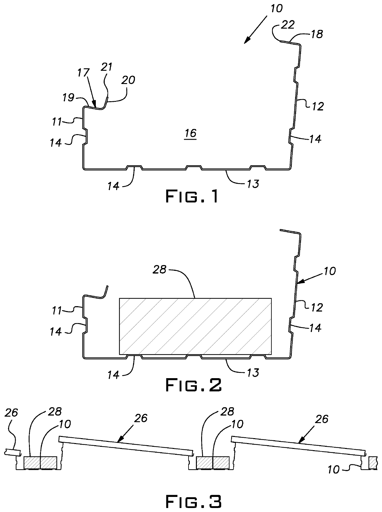
[0016]An elongated, longitudinally continuous rack channel 10 is shown in various figures. The rack channel, sometimes referred to simply as the channel, is preferably formed from a continuous strip of flat sheet metal stock. Currently, a preferred strip stock is 22 or 24 gauge steel coated with an alloy of 45% zinc and 55% aluminum marketed under the trademark GALVALUME®. Other metal stock such as galvanized steel or anodized aluminum of various gauges can be used. FIG. 1 illustrates the rack channel 10 in end view, it being understood that the cross-section of the rack channel has the same geometry and is constant along essentially the full length of the rack channel.

[0017]By way of example, but not limitation, the channel 10 has a generally rectangular cross-section with two generally upstanding legs or walls 11, 12 and a generally horizontal base or wall 13. The legs 11, 12 are of unequal heights, a short leg 11 measuring approximately 3 inches in height and a longer leg 12 meas...


PUM

PropertyMeasurementUnit
heightaaaaaaaaaa
angleaaaaaaaaaa
lengthsaaaaaaaaaa

Abstract

A one-piece elongated roll-formed sheet metal rack channel made to order on-site, for supporting solar panels, in rows of an array, at a desired inclination relative to a generally flat horizontal surface, the channel being formed of a strip of sheet metal with a horizontal base and spaced upstanding legs, the legs being of unequal height and each with lower portions integral with a respective longitudinal margin of the base, each leg having an inturned panel supporting flange at an upper longitudinal edge, the flanges having inclined panel supporting surfaces that lie in planes generally parallel to a plane of the desired inclination, the panels along a row being electrically grounded to rack channels at the row.

Description

BACKGROUND OF THE INVENTION[0001]The invention relates to solar panel support systems particularly useful on flat or nearly flat roof and ground level fields.PRIOR ART[0002]Prior art arrangements for supporting solar panels at a desired angle or orientation have primarily involved multiple parts including extrusions, bracketry, mounting tabs and numerous fasteners requiring manual on-site assembly. Besides assembly, costs associated with these prior art multiple component systems can include their separate purchase, handling, inventorying, shipping and allowances for loss, particularly of small parts. Required on-site manual assembly of prior systems adds the risk of component damage and improper installation through human error, carelessness, inattention or the like.[0003]Before delivery to a site, prior systems can require extensive measurement of the intended site, determination of obstacles which lie in the field of the solar panel array, and communication of the same to the sou...

Claims


Application Information

Patent Timeline
Patent Type & Authority Applications(United States)
IPC IPC(8): H02S30/10F16B5/06B21B1/08H02S40/34
CPCH02S30/10H02S40/34B21B1/08F16B5/0685F24S25/40F24S25/634F24S2020/14F24S2025/02H02S20/24Y02B10/10Y02E10/47Y02E10/50
Inventor SCIPIONE, DONALD S.
Owner SCIPIONE DONALD S
Features
  • R&D
  • Intellectual Property
  • Life Sciences
  • Materials
  • Tech Scout
  • Unparalleled Data Quality
  • Higher Quality Content
  • 60% Fewer Hallucinations
Learn More