Antenna apparatus, communication apparatus and steering adjustment method thereof

a multi-polar antenna and steering adjustment technology, applied in the field of antenna technology, can solve the problems of enlarge the arrangement inapplicability to electronic devices, and loss of polarization, and achieve good antenna effect and reduce the area of the antenna structur

Pending Publication Date: 2020-08-20
GEMTEK TECH CO LTD
View PDF8 Cites 0 Cited by
  • Summary
  • Abstract
  • Description
  • Claims
  • Application Information

AI Technical Summary

Benefits of technology

[0004]In view of this, embodiments of the disclosure provide an antenna apparatus, a communication apparatus, and a steering adjustment method thereof. The area of an antenna structure may be reduced, and a relatively good antenna effect may be achieved.
[0008]Based on the above, according to the antenna apparatus, the communication apparatus and the steering adjustment method thereof of the embodiments of the disclosure, a multi-polarized antenna unit capable of controlling a feeding signal vector independently / separately is provided. One or more antenna units form an antenna array structure, and for such an antenna structure, vector configurations corresponding to different polarized directions may be set individually to form beams facing the designated direction. Compared with the conventional art, the embodiments of the disclosure have the advantages that the antenna size is relatively small but a similar or better effect may be achieved.

Problems solved by technology

However, if an antenna polarized direction is different from a direction where an electromagnetic wave is received, polarization loss may be caused.
However, such designs may greatly enlarge the arrangement area of an antenna structure and further make it inapplicable to an electronic device with a compact design.

Method used


Image

  • Antenna apparatus, communication apparatus and steering adjustment method thereof
  • Antenna apparatus, communication apparatus and steering adjustment method thereof
  • Antenna apparatus, communication apparatus and steering adjustment method thereof

Examples


first embodiment

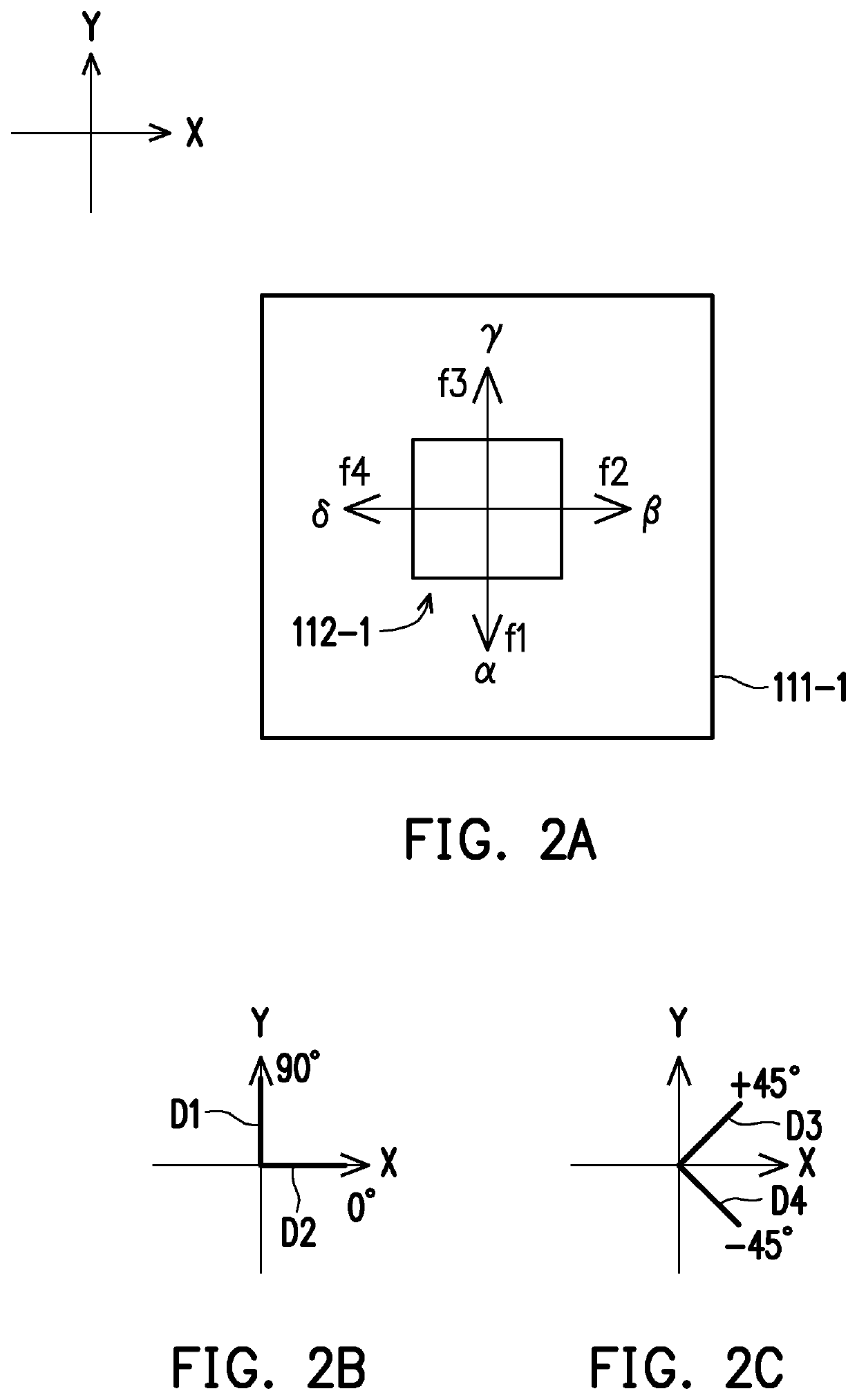
[0035]It is to be noted that each antenna unit 112 in the embodiment of the disclosure includes more than two feeding ports f1 to fi (namely i is a positive integer larger than 2). FIG. 2A is a schematic diagram of an antenna structure 111-1 according to the disclosure. Referring to FIG. 2A, the antenna structure 111-1 includes an antenna unit 112-1. The antenna unit 112-1 is a quadruple-polarized antenna, and includes four feeding ports f1 to f4 (assumed to correspond to feeding signals α, β, γ and δ respectively) respectively. It is to be noted that the four feeding ports f1 to f4 that are orthogonal to one another in the quadruple-polarized antenna may provide relatively good isolation and electric correlation coefficient (ECC) and may improve the gain better. In the present embodiment, feeding directions of the feeding ports f1 and f3 at the top and bottom of the figure extend forwards and backwards along a Y direction (namely extending directions of the two feeding ports f1 and...

second embodiment

[0058]FIG. 9A and FIG. 9B are schematic diagrams of controlling beam shapes in the elevation direction for a +45-degree polarized direction according to the disclosure. Referring to FIG. 9A and FIG. 9B, the vectors of the feeding ports f1 and f3 are adjusted, and then beams 711, 712 and 713 are in patterns formed for the directions toward the bottom, the top and the front respectively. Compared with the beam 713, the beam 711 is toward the bottom more; and compared with the beam 713, the beam 712 is toward the top more.

[0059]FIG. 9C and FIG. 9D are schematic diagrams of controlling beam shapes in the azimuth for a +45-degree polarized direction according to the second embodiment of the disclosure. Referring to FIG. 9C and FIG. 9D, the vectors of the feeding ports f1 and f3 are adjusted, and then beams 721, 722 and 723 are in patterns formed for the directions toward the left, the right and the front respectively. Compared with the beam 723, the beam 721 is toward the left more; and ...

fifth embodiment

[0064]FIG. 11A and FIG. 11B are schematic diagrams of controlling beam shapes in the elevation direction for a +45-degree polarized direction according to the disclosure. Referring to FIG. 11A and FIG. 11B, beams 811, 812 and 813 are in patterns formed for the directions toward the top, the front and the bottom respectively. Compared with the beam 812, the beam 811 is toward the top more; and compared with the beam 812, the beam 813 is toward the bottom more.

[0065]FIG. 11C and FIG. 11D are schematic diagrams of controlling beam shapes in the azimuth for a +45-degree polarized direction according to the fifth embodiment of the disclosure. Referring to FIG. 11C and FIG. 11D, beams 821, 822 and 823 are in patterns formed for the directions toward the right, the front and the left respectively. Compared with the beam 822, the beam 821 is toward the right more; and compared with the beam 822, the beam 823 is toward the left more.


PUM


Abstract

An antenna apparatus, a communication apparatus, and a steering adjustment method thereof are provided. The antenna apparatus includes an antenna structure. The antenna structure includes an antenna unit. The antenna unit includes i feeding ports, where i is a positive integer larger than 2. A vector of each of the feeding ports is controlled independently. In the steering adjustment method, a designated direction is determined, where the designated direction corresponds to beam directionality of the antenna structure. In addition, the vectors of the feeding ports of the antenna unit are configured according to the designated direction. Accordingly, the antenna size can be reduced, and beam steering in multiple directions would be achieved.

Description

CROSS-REFERENCE TO RELATED APPLICATION[0001]This application claims the priority benefits of U.S. provisional application Ser. No. 62 / 807,712, filed on Feb. 19, 2019, and Taiwan application serial no. 108129736, filed on Aug. 21, 2019. The entirety of each of the above-mentioned patent applications is hereby incorporated by reference herein and made a part of this specification.BACKGROUNDTechnical Field[0002]The disclosure relates to an antenna technology, and in particular, to a multi-polarized antenna apparatus, a communication apparatus, and a steering adjustment method thereof.Description of Related Art[0003]Electromagnetic waves emitted by an antenna may form an electric field and a magnetic field, and a direction of the electric field is an antenna polarized direction. The electromagnetic waves that may be received and / or emitted by antennae with different polarization characteristics may be different because of different antenna polarized directions. However, if an antenna po...

Claims


Application Information

Patent Timeline
Patent Type & Authority Applications(United States)
IPC IPC(8): H01Q3/34H01Q21/24
CPCH01Q3/34H01Q21/24H01Q1/36H01Q1/48H01Q1/50H01Q1/24H04B7/10H01Q21/0006H01Q21/065H01Q9/0414H01Q1/241H01Q1/2266H01Q1/2291
Inventor YANG, CHUNG-KAICHEN, SIN-LIANGWU, HSU-SHENGCHIEN, HSIAO-CHING
Owner GEMTEK TECH CO LTD
Why Eureka
Try Eureka