
High speed connector

a high-speed connector and connector technology, applied in the direction of coupling device connection, securing/insulating coupling contact member, electrical apparatus, etc., can solve the problems of electrical interference between adjacent signal conductors, affecting the performance of the system, and the electrical system generally has gotten smaller, faster and more complex, etc., to achieve high speed performance, high density interconnection, and high speed performance

Pending Publication Date: 2020-08-20
AMPHENOL CORP
View PDF1 Cites 22 Cited by
  • Summary
  • Abstract
  • Description
  • Claims
  • Application Information

AI Technical Summary

Benefits of technology

The patent describes a high-speed and high-density interconnection system. It uses a connector that has a material that helps reduce signal loss when it is connected to another connector. This results in very fast performance.

Problems solved by technology

Electronic systems generally have gotten smaller, faster, and functionally more complex.
In a high density, high speed connector, electrical conductors may be so close to each other that there may be electrical interference between adjacent signal conductors.

Method used


Image

  • High speed connector
  • High speed connector
  • High speed connector

Examples


Embodiment Construction

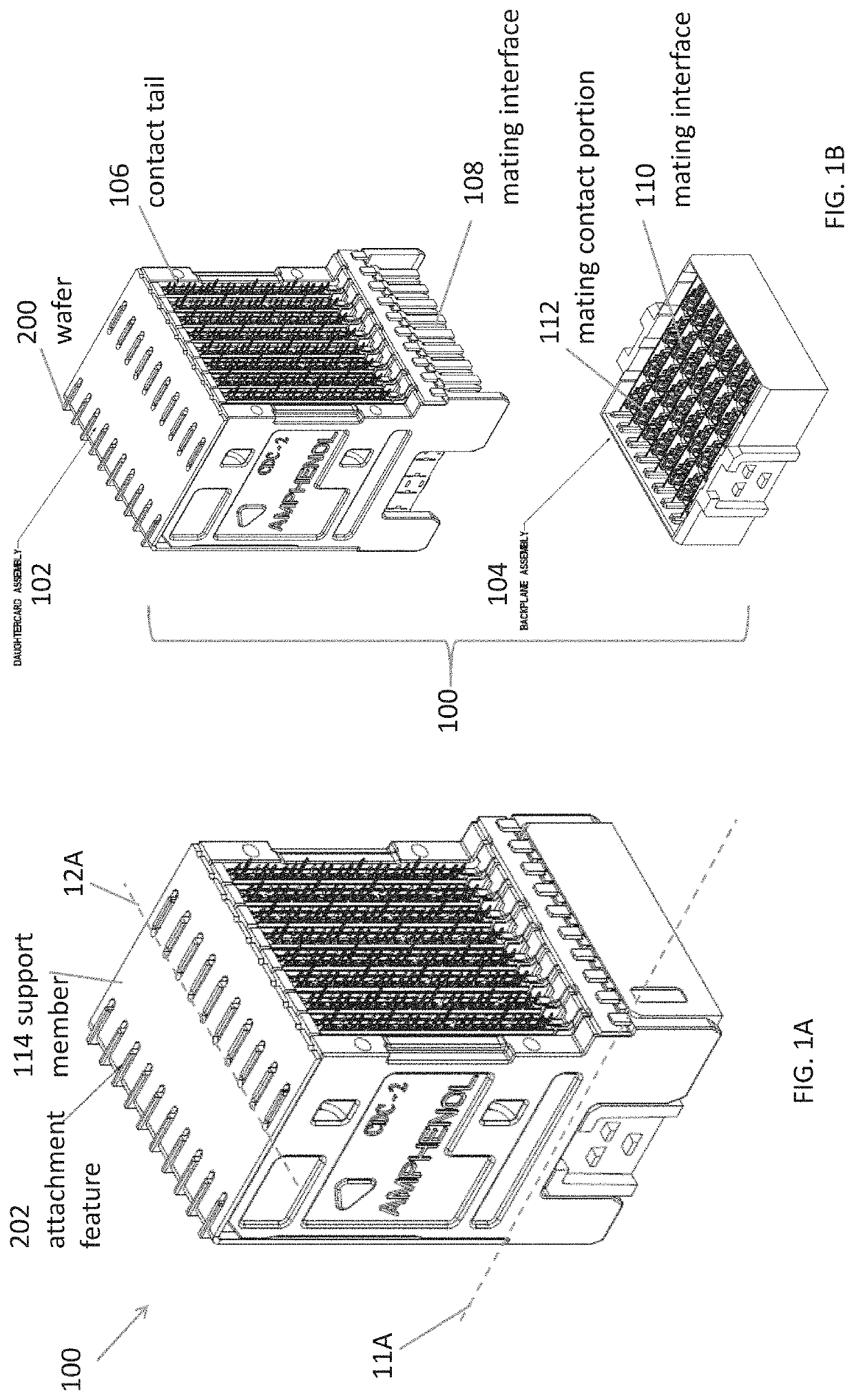
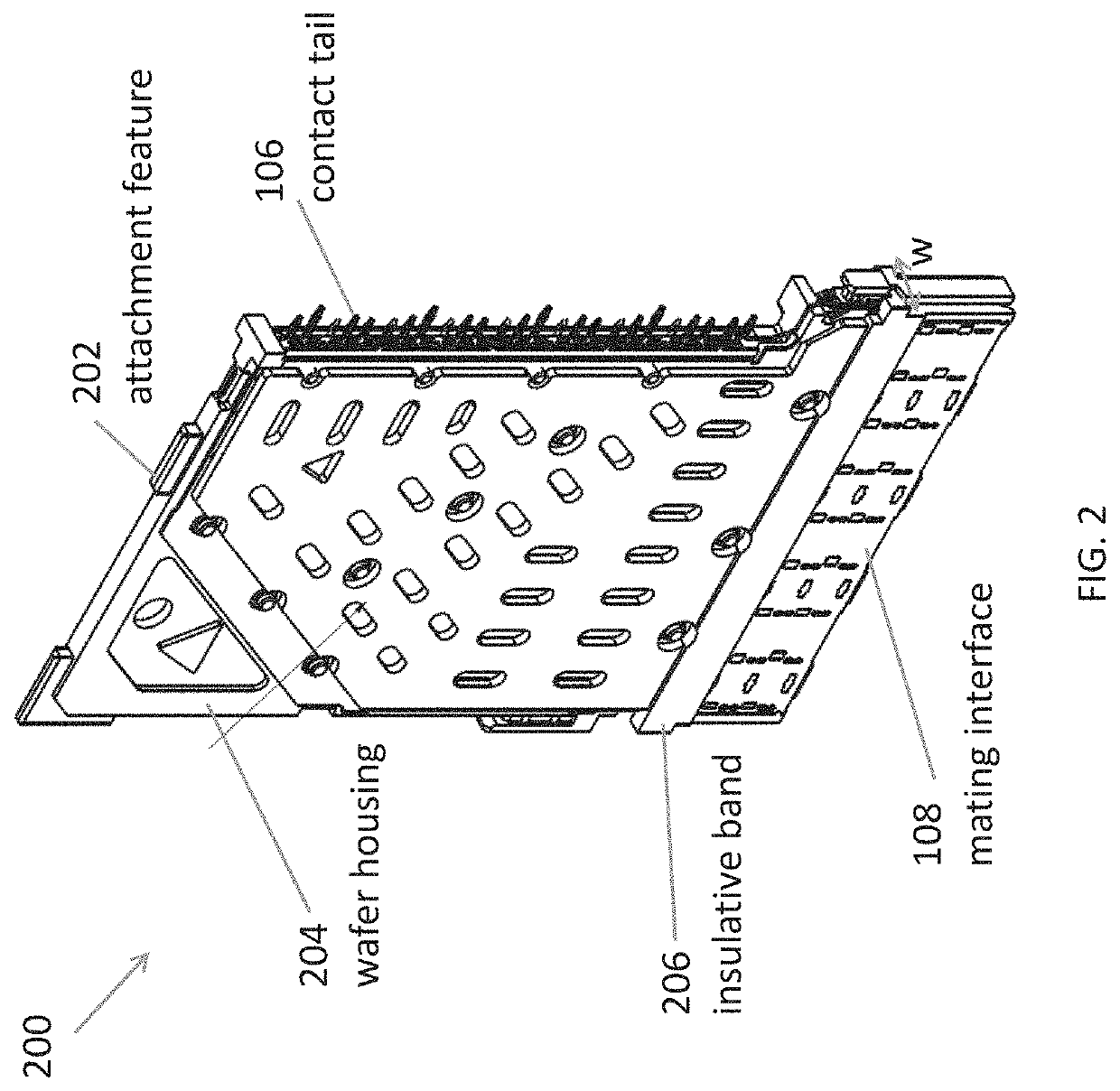
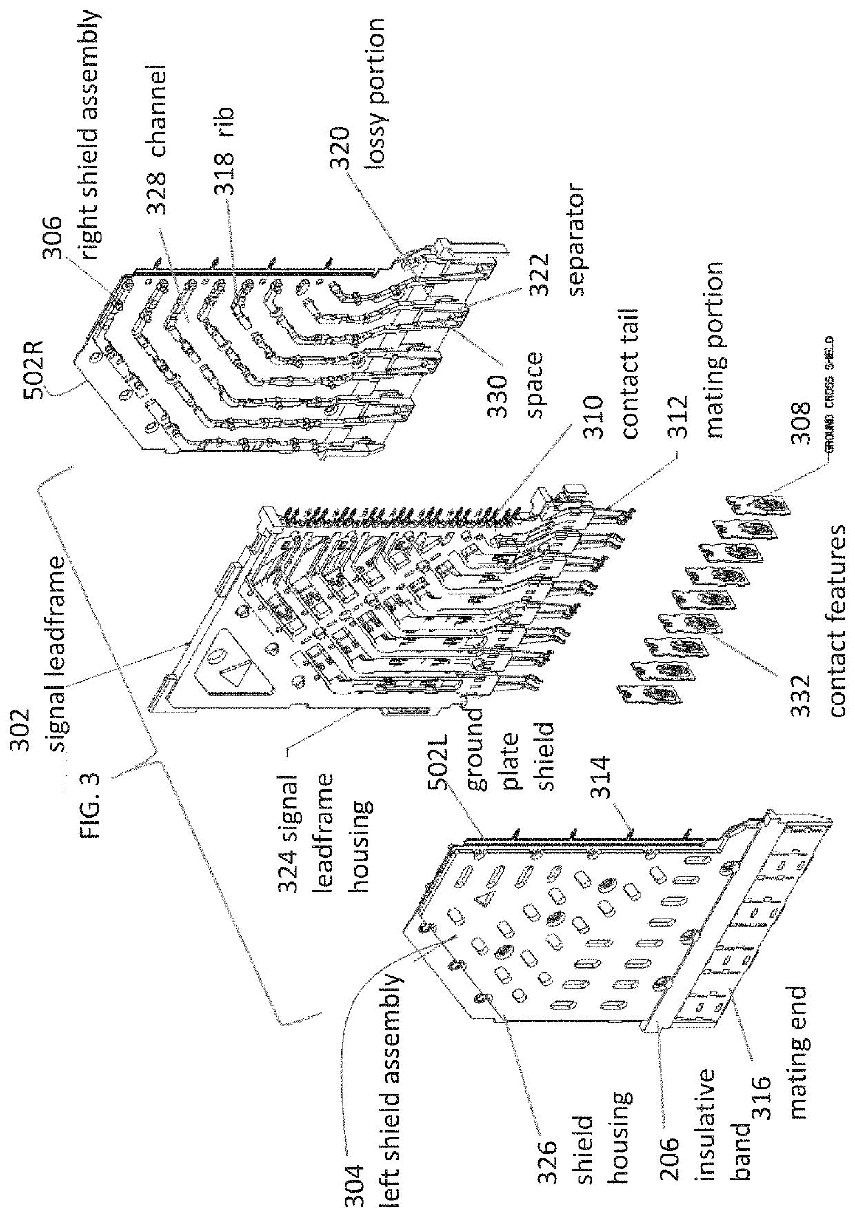
[0052]The inventors have recognized and appreciated connector designs that increase performance of a high density interconnection system, particularly those that carry very high frequency signals that are necessary to support high data rates. The connector designs may provide effective shielding in a mating region for the two connectors. When the two connectors are mated, the shielding may separate mated portions of conductive elements carrying separate signals. In some embodiments, the shielding may substantially encircle the mated portions of conductive elements carrying a signal, which may be pairs of conductive elements for connectors configured for carrying differential signals.

[0053]The inventors have recognized and appreciated that, such shielding, while effective at low frequencies may not perform as expected at high frequencies. To enable effective isolation of the signal conductors at high frequencies, the connector may include lossy material selectively positioned within ...


PUM


Abstract

An interconnection system with lossy material of a first connector adjacent a ground conductor of a second connector. The lossy material may damp resonances at a mating interface of the first and second connectors. In some embodiments, the lossy material may be attached to a ground conductor of the first connector. In some embodiments, the lossy material may be shaped as horns that extend along a cavity configured to receive a ground conductor of a mating connector.

Description

CROSS-REFERENCE TO RELATED APPLICATIONS[0001]This application claims the benefit under 35 U.S.C. § 119(e) of U.S. Provisional Patent Application Ser. No. 62 / 807,653, filed on Feb. 19, 2019 under Attorney Docket No. A0863.70116US00, entitled “HIGH SPEED CONNECTOR,” which is hereby incorporated herein by reference in its entirety.TECHNICAL FIELD[0002]This patent application relates generally to interconnection systems, such as those including electrical connectors, used to interconnect electronic assemblies.BACKGROUND[0003]Electrical connectors are used in many electronic systems. It is generally easier and more cost effective to manufacture a system as separate electronic assemblies, such as printed circuit boards (“PCBs”), which may be joined together with electrical connectors. A known arrangement for joining several printed circuit boards is to have one printed circuit board serve as a backplane. Other printed circuit boards, called “daughterboards” or “daughtercards,” may be conn...

Claims


Application Information

Patent Timeline
Patent Type & Authority Applications(United States)
IPC IPC(8): H01R13/6471H01R13/6591H01R13/652H01R13/40H01R12/72H01R13/6587
CPCH01R13/6471H01R13/40H01R13/652H01R13/6587H01R13/6591H01R12/721H01R13/502H01R13/405H01R43/24H01R13/6594H01R12/727H01R12/737H01R13/6599
Inventor PANIAGUA, JOSE RICARDOSTOKOE, PHILIP T.COHEN, THOMAS S.RICHARD, BOBMILBRAND, DONALD W.LEO, ERICGAILUS, MARK W.
Owner AMPHENOL CORP
Learn More