Multichannel transceiver of digital signals over power lines

a multi-channel, digital signal technology, applied in the direction of powerline communication systems, transmission, signal transmission/receiving via power distribution, etc., can solve the problems of destroying the information content of preamble by putting it into packets, limiting the communication rate between the modem and the microprocessor, and not being independent of the particular data format. achieve the effect of improving speed performance and low cos

Inactive Publication Date: 2005-09-27
STMICROELECTRONICS SRL
View PDF7 Cites 18 Cited by
  • Summary
  • Abstract
  • Description
  • Claims
  • Application Information

AI Technical Summary

Benefits of technology

[0015]An object of the present invention is to provide a digital data transceiving station joining together in an optimal manner the advantages of a Packet Mode transmission with the advantages of a Bit Mode transmission, thus providing enhanced speed performances even using a relatively low cost microprocessor.
[0016]The transceiving station of the invention is characterized in that during the transmission of each single data frame between the modem and the microprocessor, the serial interface switchs from a Packet Mode to a Bit Mode communication without losing data.

Problems solved by technology

It is easy to understand that the Bit Mode has the advantage of being usable irrespective of any particular data format, but its drawback is that the rate of communication between the modem and the microprocessor is limited to that of the communication channel.
However, it is not independent of the particular data format.
For example, if the protocol format has data in frames being transmitted with a preamble followed by a header and by a data field alternated with synchronization signals, formatting the preamble into packets would destroy its information content.
This would waste the benefits of the greater communication speed that may be achieved with a Packet Mode transmission.

Method used


Image

  • Multichannel transceiver of digital signals over power lines
  • Multichannel transceiver of digital signals over power lines
  • Multichannel transceiver of digital signals over power lines

Examples


Embodiment Construction

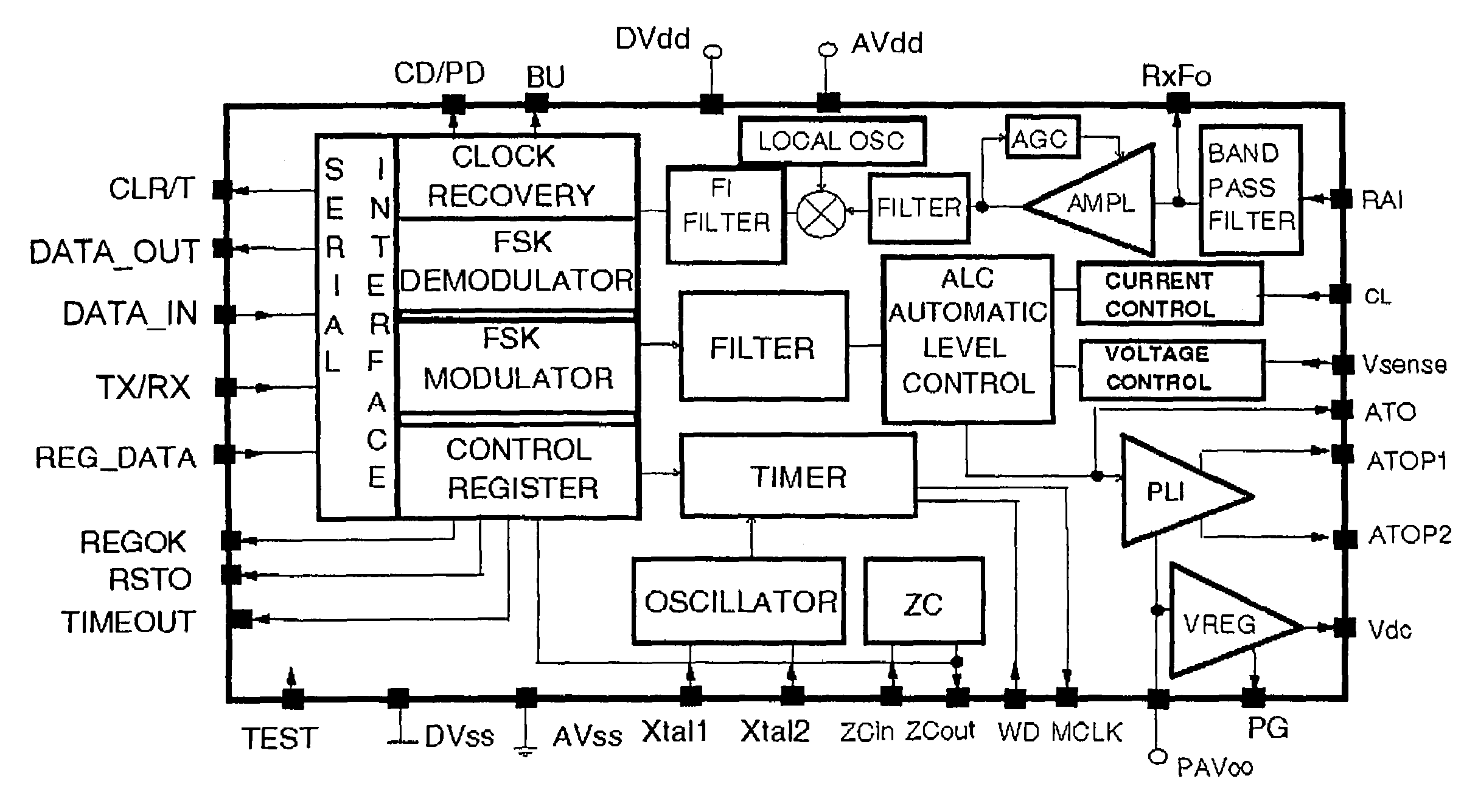
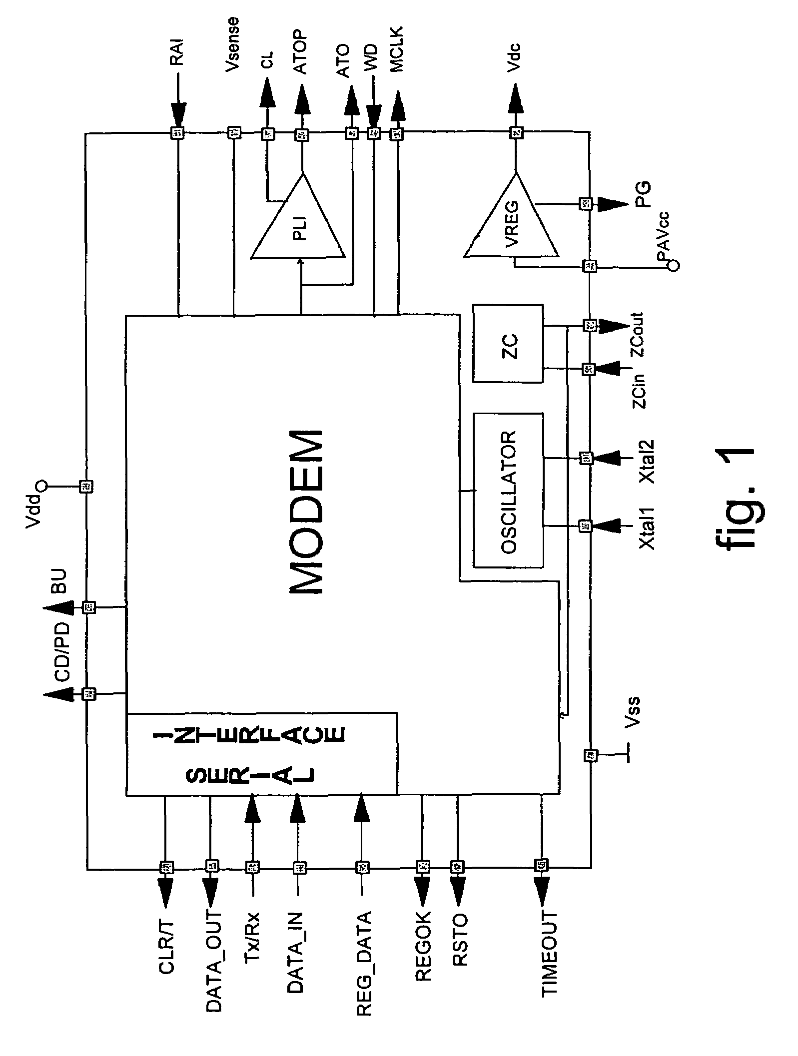
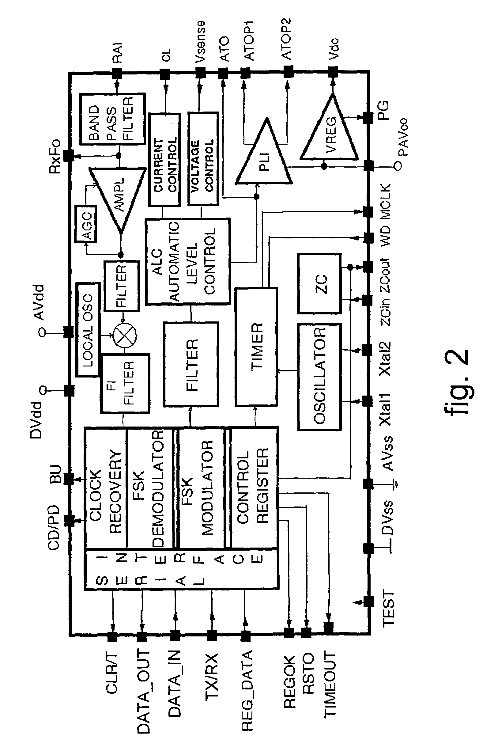
[0029]The integrated transceiver of the invention is depicted schematically in FIG. 1, and is formed by a digital modem MODEM which may be a frequency shift keying (FSK) modem, for example. A serial interface circuit SERIAL—INTERFACE allows the modem to communicate external the integrated transceiver. The integrated transceiver further includes an oscillator OSCILLATOR providing carrier frequencies to the modem, a power interface PLI for driving an external coupling circuit to a line of the electrical power distribution network, and a zero-cross detector ZC of the network voltage. Optionally, a monolithically integrated voltage regulator VREG is also present for powering other ICs that may be present in the transceiving station.

[0030]During a receiving phase, the signal derived from the power network line is received on the pin RAI, demodulated and made available on the pin DATA—OUT. Optionally, the transceiver may produce on the pin CLR / T a clock signal for bit synchronization. The...


PUM


Abstract

A data transceiving station of digital data frames includes a digital modem coupled to a transmission line, and a microprocessor receiving demodulated data from the modem according to a Packet Mode or a Bit Mode transmission through an interface circuit. The interface circuit switches between the Packet Mode and the Bit Mode transmission during transfer of a data frame to the microprocessor. The data transceiving station combines the superior speed of a Packet Mode transfer with the unlimited compatibility of a Bit Mode transfer.

Description

FIELD OF THE INVENTION[0001]The present invention relates to data transmission systems, and, more particularly, to a digital signal transceiver for home applications, specially, though not exclusively, coupled to an electrical power distribution line.BACKGROUND OF THE INVENTION[0002]Electric power distribution networks are widespread and are capillary like. These networks primarily transport and distribute electric energy, but the possibility of exploiting it also as a medium for data transmission is well known. Electrical mains can be advantageously used to establish communication with far away locations exploiting the fact that even remote rural users are reached by an electrical power line. It is also possible to avoid the cost of a dedicated line (e.g., a telephone line) for telecommunications.[0003]Data transmission on electrical mains is possible since AC power is distributed with a well determined frequency. Signal modulation techniques permit the transmission of information ...

Claims


Application Information

Patent Timeline
Patent Type & Authority Patents(United States)
IPC IPC(8): H04B3/54
CPCH04B3/54H04B2203/5408H04B2203/542H04B2203/5437H04B2203/5458H04B2203/5483H04B2203/5491
Inventor CAPPELLETTI, ROBERTOCANTONE, GIUSEPPE
Owner STMICROELECTRONICS SRL
Why Eureka
Try Eureka