Thrust roller bearing

a technology of thrust roller bearing and roller bearing, which is applied in the direction of rolling contact bearing, rotary bearing, shaft and bearing, etc., can solve the problems of low torque characteristics of bearings, and achieve the effect of reducing sliding frictional resistance at the contact portion between the roller and the cage and low torque characteristics of thrust roller bearings

Active Publication Date: 2020-08-27
JTEKT CORP
View PDF0 Cites 0 Cited by
  • Summary
  • Abstract
  • Description
  • Claims
  • Application Information

AI Technical Summary

Benefits of technology

[0013]With the present disclosure, the sliding frictional resistance at the contact portion between the roller and the cage is reduced, which achieves the low torque characteristics of the thrust roller bearing.

Problems solved by technology

When a sliding frictional resistance at the contact portion between the cage pocket and the roller increases, low torque characteristics of the bearing deteriorate.

Method used


Image

  • Thrust roller bearing
  • Thrust roller bearing
  • Thrust roller bearing

Examples


Embodiment Construction

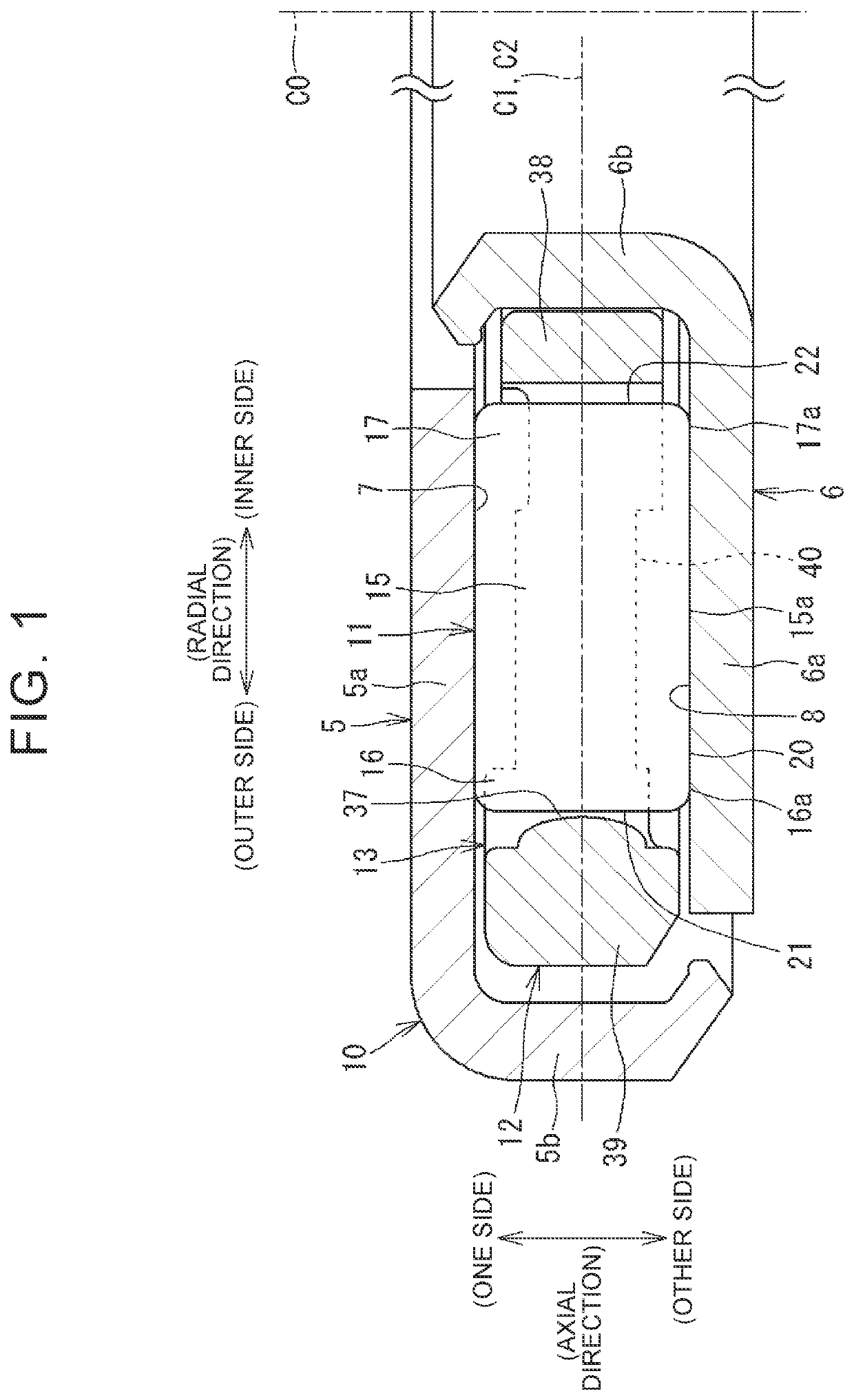
[0021]FIG. 1 is a cross-sectional view showing an example of a thrust roller bearing. A thrust roller bearing 10 (hereinafter also simply referred to as “bearing 10”) shown in FIG. 1 includes an annular cage 12 and a plurality of rollers 11. The bearing 10 of a present disclosure further includes an annular first bearing ring (housing bearing washer) 5 disposed on an one side of the bearing 10 in an axial direction of the bearing 10 (the upper side in FIG. 1) and a second bearing ring (shaft bearing washer) 6 disposed on the other side of the bearing 10 in the axial direction (the lower side in FIG. 1).

[0022]The first bearing ring 5 and the second bearing ring 6 rotate relative to each other about an central axis C0 of the bearing 10. In the present disclosure, a direction along the central axis C0 of the bearing 10 is referred to as “axial direction”. The term “axial direction” includes a direction parallel to the central axis C0. A direction orthogonal to the central axis C0 is de...


PUM


Abstract

A thrust roller bearing includes a plurality of rollers and a cage including a plurality of cage pockets for housing the rollers. The rollers each include a cylindrical portion, an outer crowning portion, and an inner crowning portion. The cage pockets each include an outer surface, an inner surface facing a second end surface of the roller, and a pair of side surfaces facing an outer peripheral surface of the roller. The side surfaces each include a recessed surface that is not contactable with the roller, and flat surfaces that are provided on the outer side in the radial direction and on the inner side in the radial direction, respectively, and are contactable with the roller. A first dimension is larger than a second dimension.

Description

INCORPORATION BY REFERENCE[0001]The disclosure of Japanese Patent Application No. 2019-034293 filed on Feb. 27, 2019 and Japanese Patent Application No. 2019-033896 filed on Feb. 27, 2019, each including the specification, drawings and abstract, is incorporated herein by reference in its entirety.BACKGROUND1. Technical Field[0002]The present disclosure relates to a thrust roller bearing.2. Description of Related Art[0003]Thrust roller bearings are able to receive an axial load generated between a first member and a second member that rotate relative to each other. The thrust roller bearings are able to be downsized especially when rollers are needle rollers. Further, the thrust roller bearings can cope with rotation at a high speed and have large load capacity. The thrust roller bearings are applied to transmission devices of an automobile and an industrial construction machine, and also widely used in other rotary devices (refer to Japanese Unexamined Patent Application Publication...

Claims


Application Information

Patent Timeline
Patent Type & Authority Applications(United States)
IPC IPC(8): F16C33/46F16C19/30
CPCF16C19/305F16C33/467F16C2326/06F16C19/30F16C33/30F16C33/46F16C33/583F16C33/4676F16C33/4682F16C33/547F16C2300/22F16C33/34F16C33/4605
Inventor SHISHIHARA, YUKIKAMAMOTO, SHIGEOMURATA, JUNJI
Owner JTEKT CORP
Why Eureka
Try Eureka