
Method And Apparatus For Fluorescence Lifetime Measurement

a technology of fluorescence lifetime and measurement method, applied in the field of methods and apparatus for fluorescence lifetime measurement, can solve the problems of increasing the power consumption required to measure the fluorescence lifetime, inefficient temporal measurement of fluorescence lifetime, and loss of energy in the absence of light of emission

Active Publication Date: 2020-08-27
NOKIA TECHNOLOGLES OY
View PDF0 Cites 1 Cited by
  • Summary
  • Abstract
  • Description
  • Claims
  • Application Information

AI Technical Summary

Benefits of technology

The patent describes a method, apparatus and computer program for determining the fluorescence lifetime of a sample by measuring the electric charge generated by fluorescence emission during two overlapping time periods. The method involves storing the electric charge generated during the two time periods and comparing it to a threshold to determine the fluorescence lifetime. The apparatus includes multiple storage devices and a computing device for this purpose. The technical effect of this patent is to provide a more efficient and accurate method for determining the fluorescence lifetime of a sample.

Problems solved by technology

These photophysical events include internal conversion or vibrational relaxation, both of which result in the loss of energy in the absence of light of emission.
However, the measurement of fluorescence lifetime may be inefficient from a temporal perspective, at least in instances in which the fluorescence is relatively weak.
However, the process of collecting the photocharges in the two separate time windows requires multiple measurement cycles, with the number of measurement cycles increasing in instances in which the fluorescence is relatively weak such that multiple measurement cycles are required to capture a sufficient quantity of the photocharges for measurement purposes.
In addition, the increased number of measurement cycles required to measure the fluorescence lifetime also increases the power consumption required to measure the fluorescence lifetime.
In this regard, a sensor, such as a light-sensitive diode, must be powered on during each measurement cycle in order to receive the incident light such that an increase in the number of measurement cycles correspondingly increases the power consumed by the sensor.

Method used


Image

  • Method And Apparatus For Fluorescence Lifetime Measurement
  • Method And Apparatus For Fluorescence Lifetime Measurement
  • Method And Apparatus For Fluorescence Lifetime Measurement

Examples


Embodiment Construction

[0028]Some embodiments of the present invention will now be described more fully hereinafter with reference to the accompanying drawings, in which some, but not all, embodiments of the invention are shown. Indeed, various embodiments of the invention may be embodied in many different forms and should not be construed as limited to the embodiments set forth herein; rather, these embodiments are provided so that this disclosure will satisfy applicable legal requirements. Like reference numerals refer to like elements throughout. As used herein, the terms “data,”“content,”“information,” and similar terms may be used interchangeably to refer to data capable of being transmitted, received and / or stored in accordance with embodiments of the present invention. Thus, use of any such terms should not be taken to limit the spirit and scope of embodiments of the present invention.

[0029]Additionally, as used herein, the term ‘circuitry’ refers to (a) hardware-only circuit implementations (e.g.,...


PUM

PropertyMeasurementUnit
fluorescenceaaaaaaaaaa
fluorescence lifetimeaaaaaaaaaa
electric chargeaaaaaaaaaa

Abstract

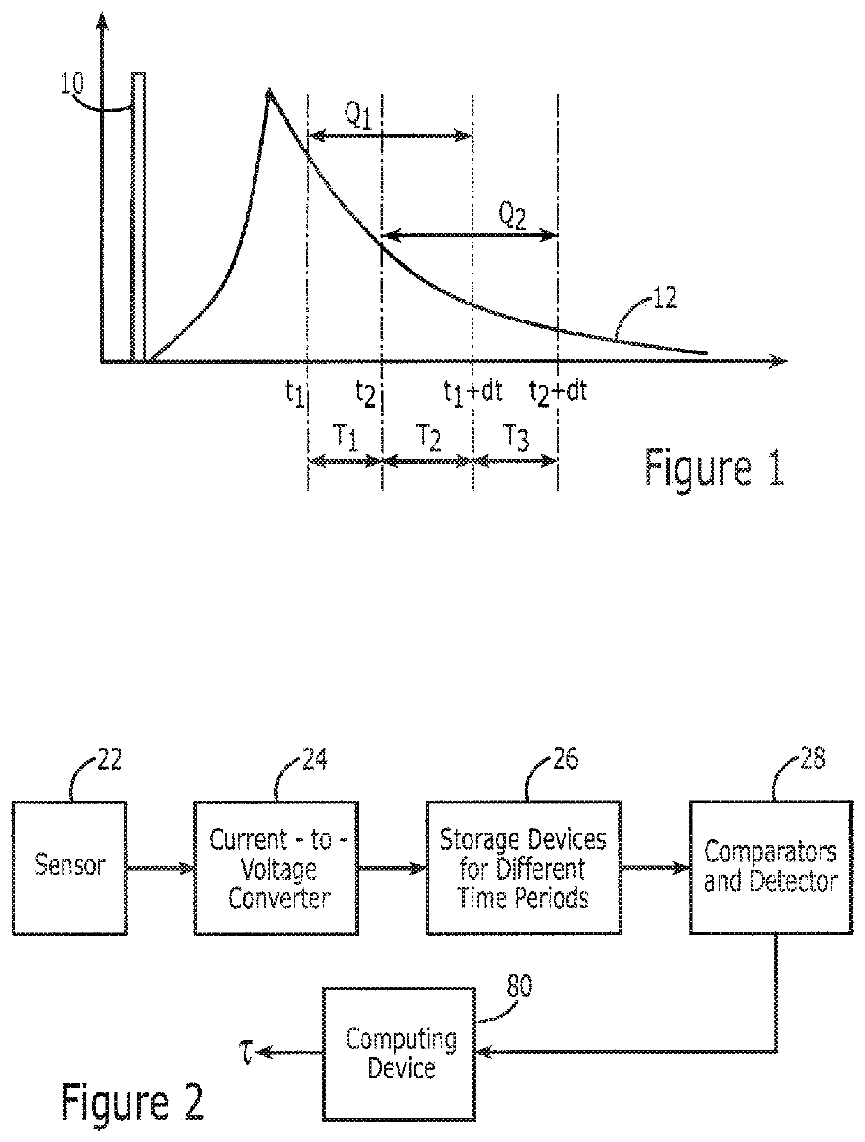
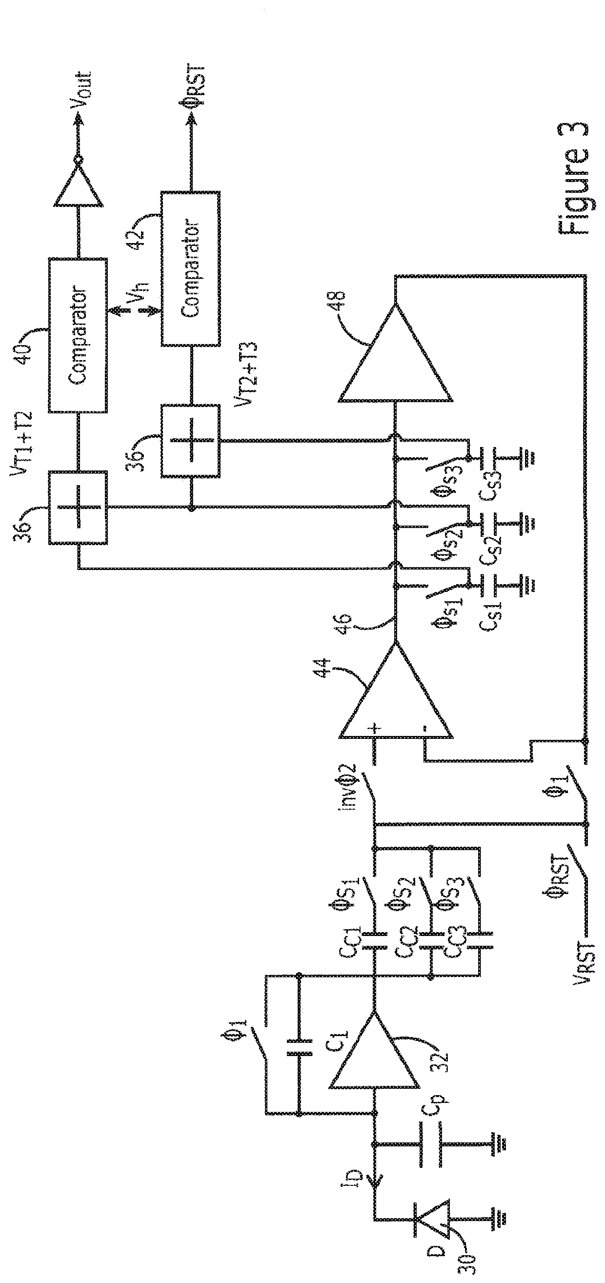
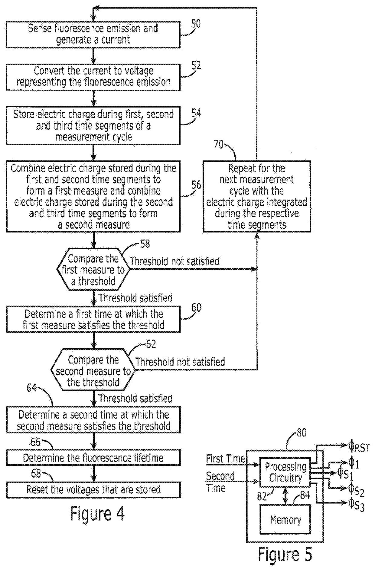
A method, apparatus and computer program product are provided to determine the fluorescence lifetime in an efficient manner In the context of a method electric charge generated by fluorescence emission during two overlapping time periods of a single measurement cycle is stored to form first and second measures. The electric charge generated during that segment of the two time periods during which the two time periods overlap is incorporated in the first measure and in the second measure. The method also includes determining a fluorescence lifetime based at least in part upon the first and second measures.

Description

TECHNOLOGICAL FIELD[0001]An example embodiment relates generally to a method, apparatus and computer program product for fluorescence lifetime measurement and, more particularly, to a method, apparatus and computer program product for determining the fluorescence lifetime based upon the electric charge generated by fluorescence emission during two overlapping periods of a single measurement cycle.BACKGROUND[0002]Various measures of fluorescence, such as fluorescence intensity and fluorescence lifetime, may be employed for a variety of purposes including the analysis of various materials, including applications involving oxygen sensing and various biological and medical applications. In this regard, in an instance in which a molecule absorbs a photon of appropriate energy, a chain of photophysical events is triggered. These photophysical events include internal conversion or vibrational relaxation, both of which result in the loss of energy in the absence of light of emission. The ch...

Claims


Application Information

Patent Timeline
Patent Type & Authority Applications(United States)
IPC IPC(8): G01N21/64
CPCG01N2021/6463G01N21/645G01N21/6408G01N2201/12G01J3/4406G01J1/46G01J2001/446G01J2001/4433
Inventor HERCEG, MARIJANMATIC, TOMISLAV
Owner NOKIA TECHNOLOGLES OY
Learn More