
Radiationless hair dryer

a hair dryer and radiation-free technology, applied in the field of hair dryers, can solve the problems of generating a large amount of radiation in use, affecting the use of hair dryers, so as to reduce the effect of radiation generation

Inactive Publication Date: 2020-09-03
HSU ANNIE
View PDF0 Cites 7 Cited by
  • Summary
  • Abstract
  • Description
  • Claims
  • Application Information

AI Technical Summary

Benefits of technology

The present disclosure provides a radiationless hair dryer that reduces and eliminates the radiation generated by a hair dryer. The technical effects include the formation of a magnetic field shielding enclosed space without leakage, the leakage of electromagnetic radiation through the shielding housing and metal air outlet net, the counteracting of electromagnetic fields generated by the first and second electrically heated wires, the elimination of electric field radiation generated by the power cord, and the reduction of radiation generated by the brushless motor. These measures achieve the objective of reducing and eliminating the radiation generated by the hair dryer.

Problems solved by technology

Because people usually need to care the hair, the use frequency of the hair dryer is high, and if people use such hair dryer for a long term, their head will suffer a large amount of electromagnetic radiation so as to affect the health of people.
However, all of these schemes only solve the radiation locally and have deficiencies in the aspect of eliminating radiation of the hair dryer, and hair dryers utilizing the schemes of the prior art still generate a large amount of radiation in use.
Moreover, all of these schemes of the prior art are provided to reduce or eliminate the generated radiation, and there are no new schemes to avoid radiation generation.

Method used


Image

  • Radiationless hair dryer
  • Radiationless hair dryer
  • Radiationless hair dryer

Examples


Embodiment Construction

[0030]The technical scheme of the present disclosure is further described below in detail in conjunction with accompanying drawings and embodiments.

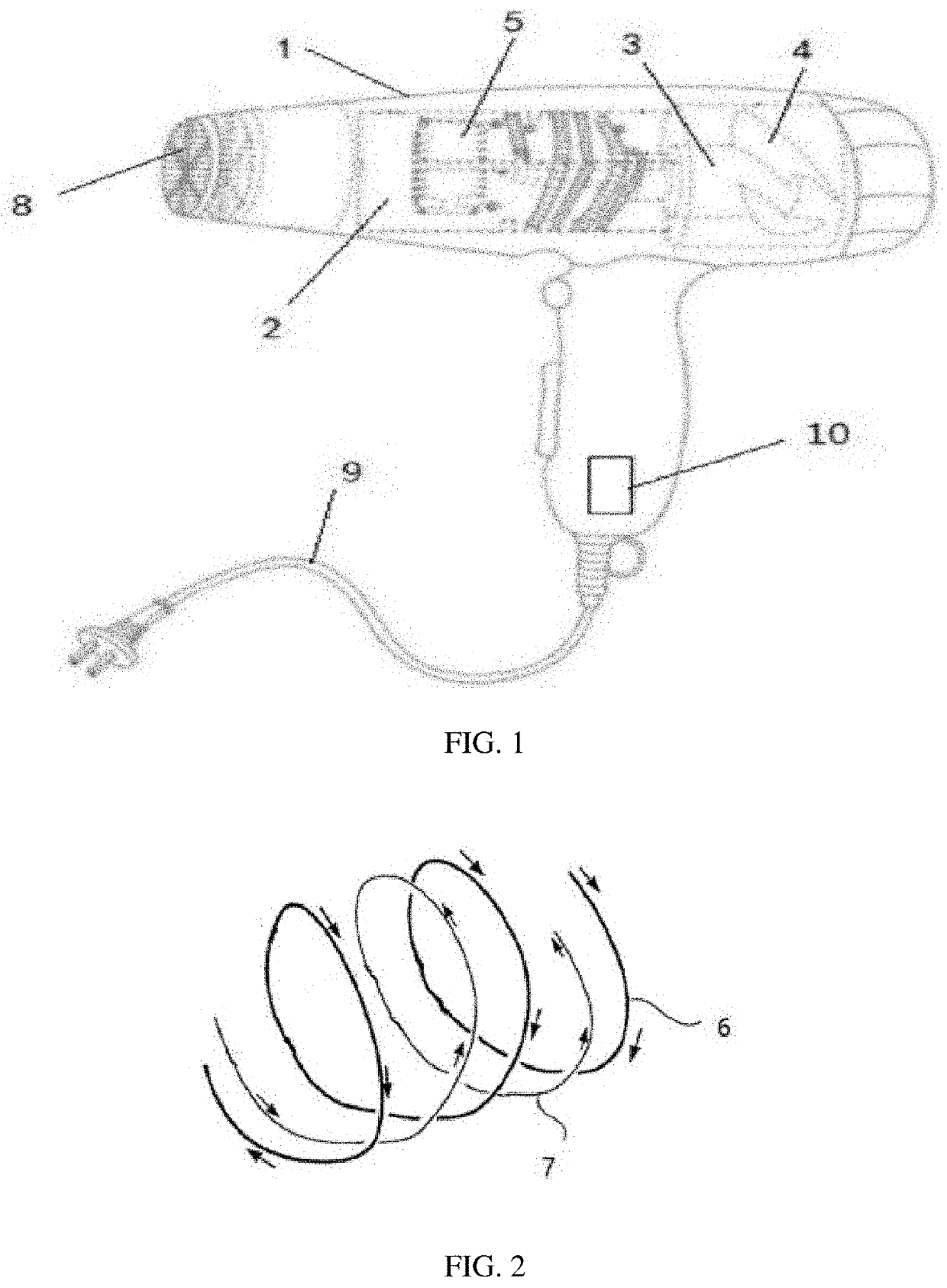
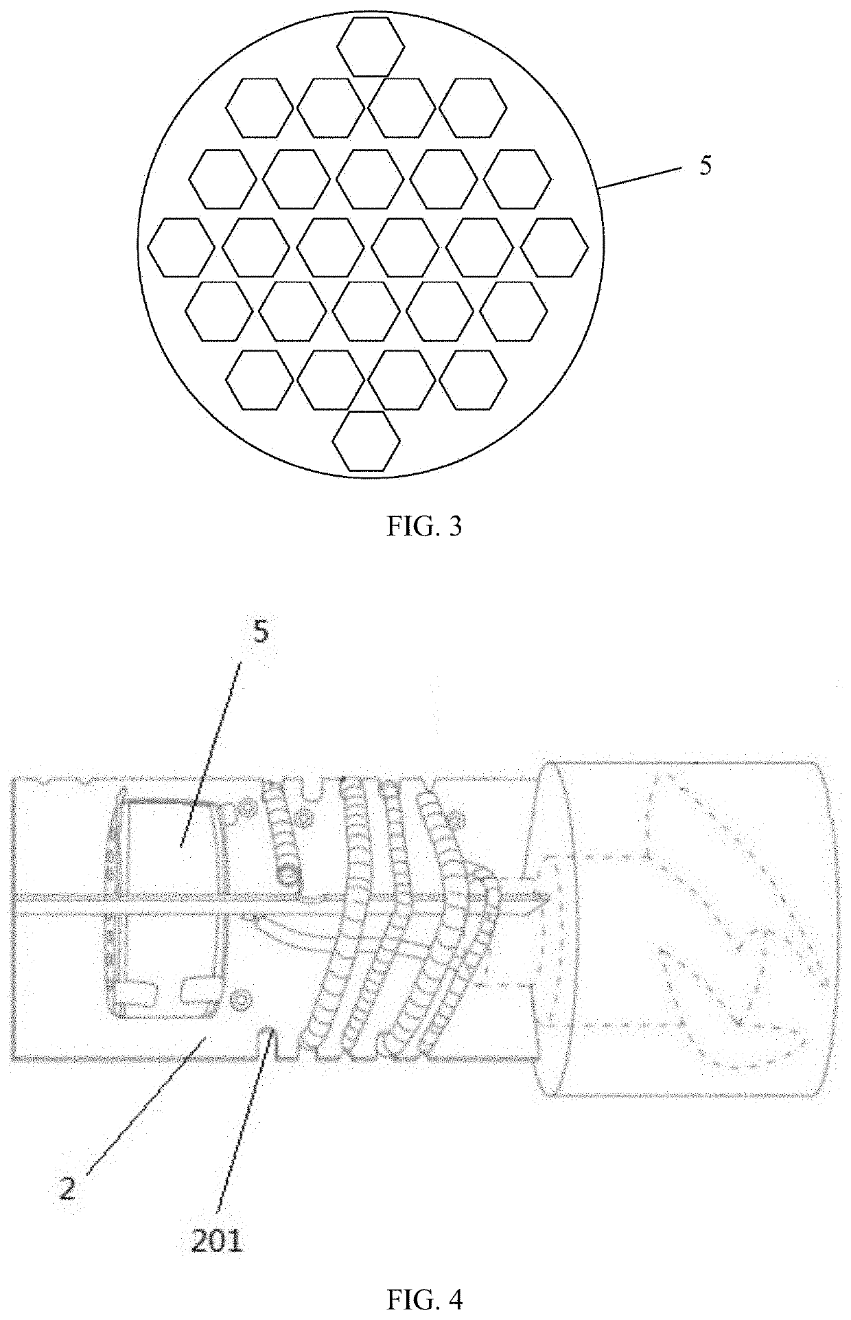
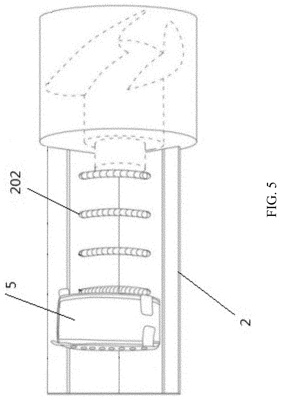
[0031]As shown in FIG. 1, FIG. 2 and FIG. 3, the present disclosure provides a radiationless hair dryer, which comprises a shielding housing 1, a mica frame 2, a brushless motor 3, a blade 4, honeycomb ceramic 5, a first electrically heated wire 6, a second electrically heated wire 7, a metal air outlet net 8, a power cord 9 and an AC / DC switching module 10;[0032]the mica frame 2 is disposed in the shielding housing 1, the honeycomb ceramic 5 is clamped at the front end of the mica frame 2, the brushless motor 3 is arranged at the back end of the mica frame 2, the blade 4 is arranged on a motor shaft of the brushless motor 3, the brushless motor 3 is connected with the AC / DC switching module 10, and the AC / DC switching module 10 is connected with the power cord 9;[0033]the metal air outlet net 8 is arranged at an air outlet of the shield...


PUM


Abstract

The present disclosure relates to a radiationless hair dryer, and belongs to the field of hair dryers. In the radiationless hair dryer, a magnetic field shielding enclosed space without leakage is formed by a shielding housing and a metal air outlet net at an air outlet of the shielding housing; the shielding housing and a brushless motor are connected with an earth wire so as to leak electromagnetic radiation; a first electrically heated wire and a second electrically heated wire are respectively and mutually alternatively wound around a mica frame in the same direction, and the direction of current flowing the first electrically heated wire and the direction of current flowing the second electrically heated wire are opposite, so that an electromagnetic field generated by the first electrically heated wire and an electromagnetic field generated by the second electrically heated wire are counteracted with each other.

Description

BACKGROUND OF THE INVENTIONField of the Invention[0001]The present disclosure belongs to the field of hair dryers, and specifically relates to a radiationless hair dryer.Description of the Related Art[0002]The hair dryer consists of a group of electrically heated wires and a blade which are arranged in a housing. When the hair dryer is powered on, the electrically heated wires generate heat, the blade rotates to blow the heat out, and at this time, the hair dryer blows hot wind out; when people do not need the hot wind, they only need to press a switching button on the housing, and at this time, the electrically heated wires do not generate the heat and the blade rotates to blow cold wind out; and when an air outlet of the hair dryer is putted to the hair to blow, the hair may be dried.[0003]In the prior art, a conventional hair dryer generates heat by heating electrically heated wires, wherein the electrically heated wires are made from Fe—Cr—Al alloy or Ni—Cr electrical thermal al...

Claims


Application Information

Patent Timeline
Patent Type & Authority Applications(United States)
IPC IPC(8): A45D20/12H05K9/00
CPCA45D20/12H05K9/0081H05K9/0075A45D20/10A45D2200/205
Inventor HSU, ANNIE
Owner HSU ANNIE
Learn More