This helps you quickly interpret patents by identifying the three key elements:
Problems solved by technology
Method used
Benefits of technology
Benefits of technology
The present invention provides a device that can adjust the focus of an eye by using the tension of a muscle called the Zinn's zonule which is connected to the lens capsule. The device has two support portions that press against the inner surface of the capsule to expand it and create a larger optical portion. This allows the device to capture and amplify the minute movement of the lens capsule, resulting in a practical focus adjustment function. In addition, the device can be designed to move the optical portion forward or backward for near or distance vision, by adjusting the pressing force on the support portions.
Problems solved by technology
However, on the other hand, it has been found that the cortex and nucleus, which are contents of the lens L, harden and lose flexibility when advancing age, and the curvature of the anterior surface of the lens L becomes difficult to change, thereby losing the ability to adjust the focal point voluntarily from the distance vision to the near vision (this is called “presbyopia”).
Method used
Image
Click on the blue label to locate the original text in one second.
Reading with bidirectional positioning of images and text.
Examples
first embodiment
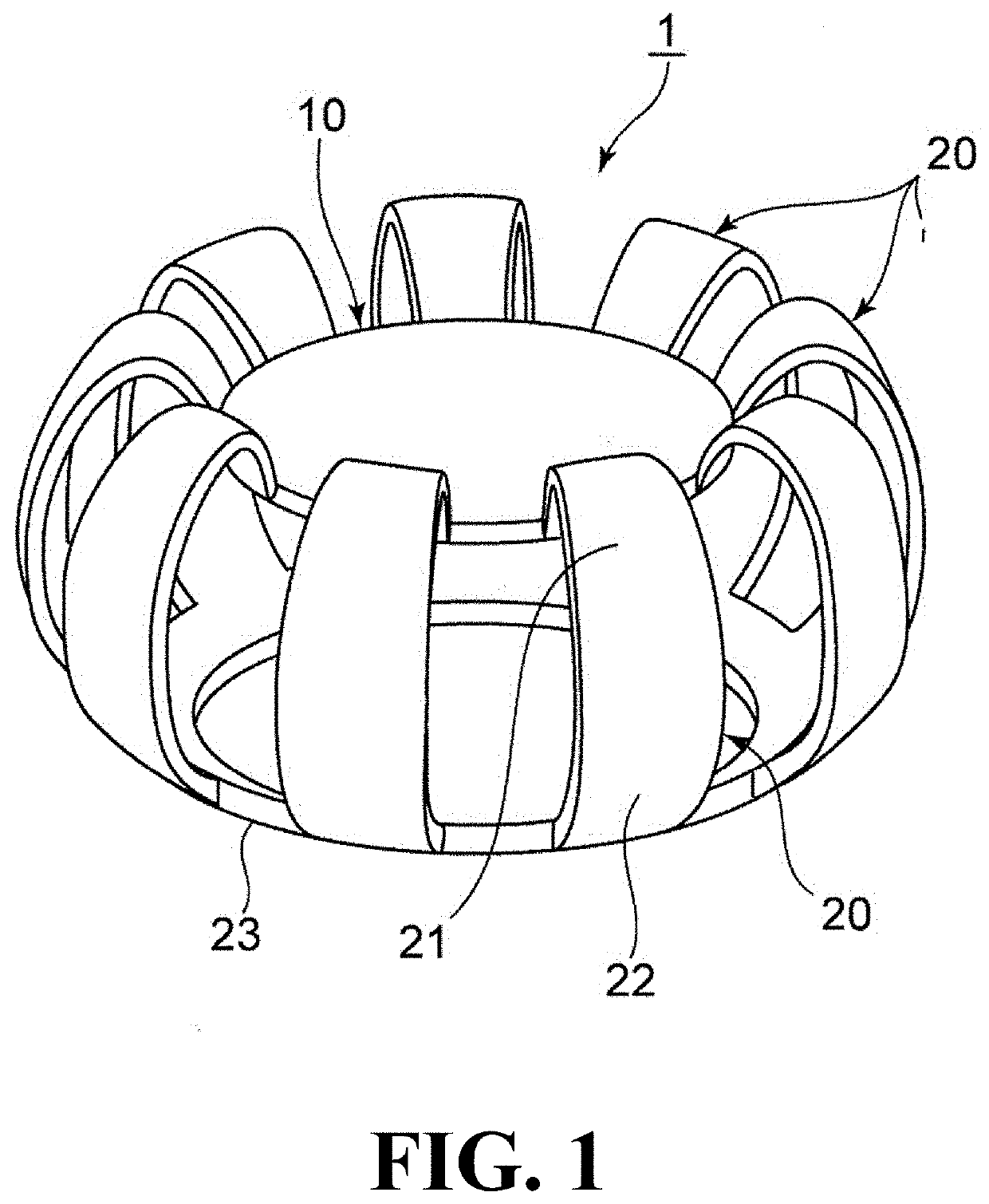
[0041]Next, with reference to FIG. 1 to FIG. 5, a first embodiment of an accommodative intraocular lens according to the present invention (hereinafter referred to as this lens 1) will be described. Note that the following description will be made assuming that the upper side of each drawing denotes a front side of a human eye, and the lower side of each drawing denotes a rear side of the human eye.
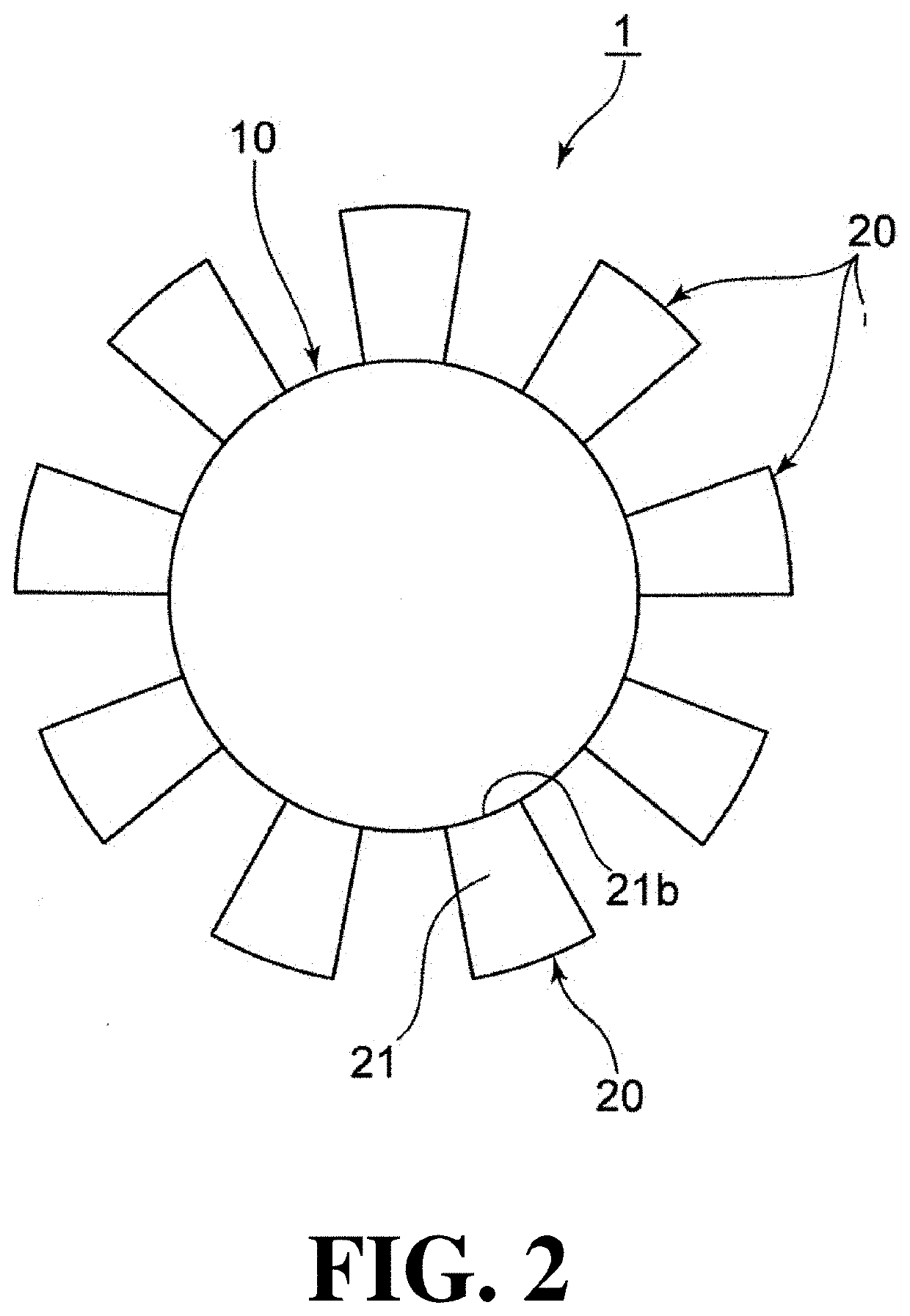
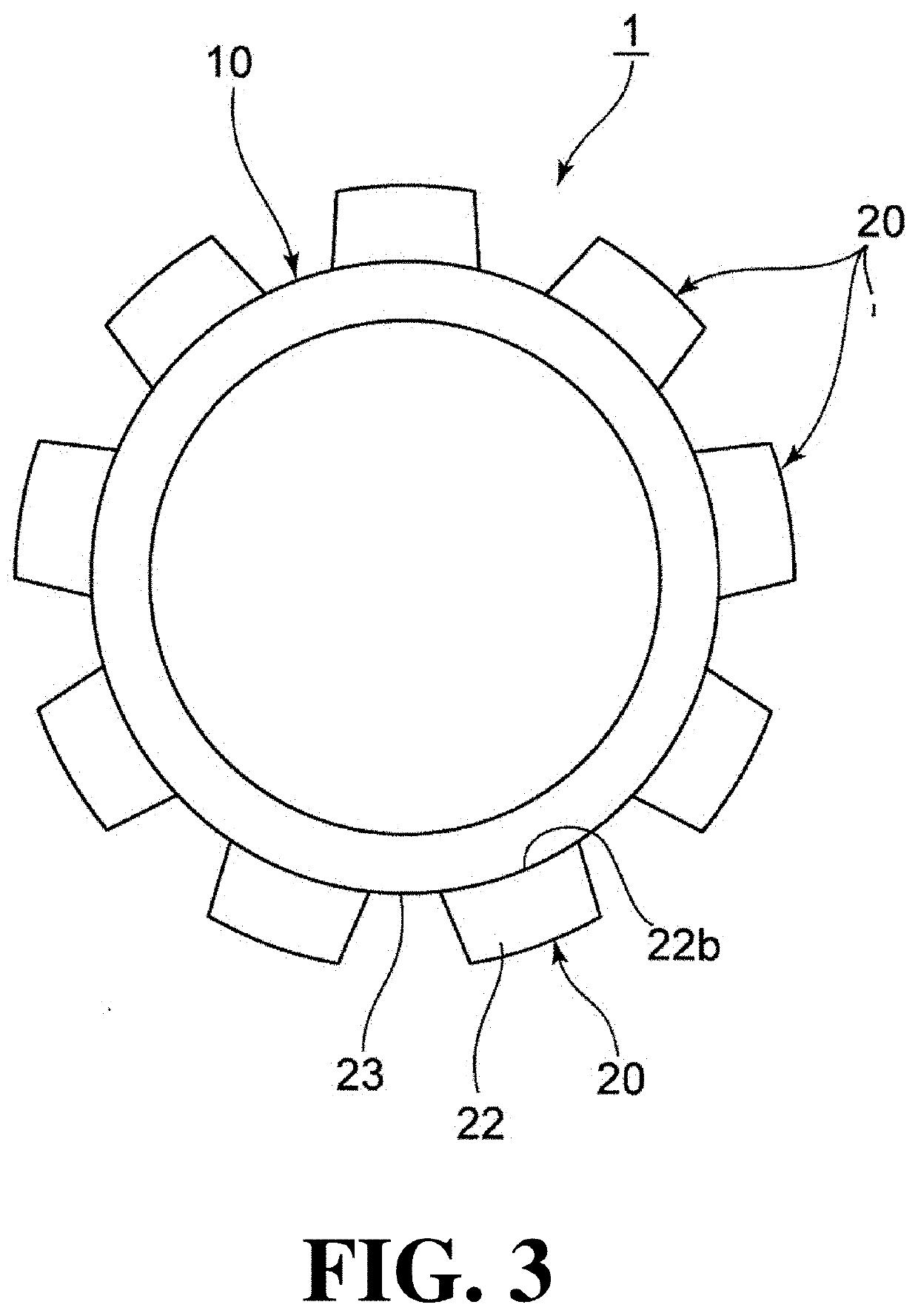
[0042]As shown in FIG. 1 to FIG. 4, this lens 1 is provided with an optical portion 10 and nine support portions 20 arranged around the optical portion 10 to support the optical portion 10, and is used by being installed in a lens capsule S whose anterior capsule has been incised in ophthalmic surgery as shown in FIG. 5.
[0043]The optical portion 10 is a convex lens made of a synthetic resin material, such as, e.g., silicone, acryl, hydrogel, PMMA, HEMA, and hydro-polymer, and has a diameter w1 of 4 mm to 7 mm in a plan view. The shape and material of the optical portion 10 are not limited...
second embodiment
[0065]Next, a second embodiment of this lens 1 will be described with reference to FIG. 6. In the following description, only configurations different from the above-described embodiment will be described, and the same reference numeral will be given to the same configuration without description.
[0066]In this embodiment, the anterior support portion 21 is provided with a regulating member 25 for maintaining the radial position of the base end portion 21a connected to the posterior support portion 22. The regulating member 25 is formed in such a manner that the base end portions 21a of the adjacent anterior support portions 21 are circumferentially connected to each other.
[0067]This restricts the anterior support portion 21 from moving radially outward of the base end portion 21a, so that it is possible to reliably deflect the anterior support portion 21 backward or return forward while maintaining the position of the base end portion 21a in the radial direction.
third embodiment
[0068]Next, a third embodiment of this lens 1 will be described with reference to FIG. 7.
[0069]In this embodiment, the anterior support portion 21 is provided with a regulating member 26 for maintaining the radial position of the base end portion 21a connected to the posterior support portion 22. The regulating member 26 is formed in such a manner as to project radially outward at a height position of the lens capsule equatorial portion Se on the outer peripheral surface of the anterior support portion 21, and is arranged so as to come into contact with the lens capsule equatorial portion Se.
[0070]This restricts the anterior support portion 21 from moving radially outward of the base end portion 21a, so that it is possible to reliably deflect the anterior support portion 21 backward or return forward while maintaining the position of the base end portion 21a in the radial direction.
PUM
Abstract
An accommodative intraocular lens capable of effectively exerting a focus adjustment function includes an optical portion and a plurality of support portions arranged around the optical portion. The support portion includes an anterior support portion and a posterior support portion, and the anterior support portion presses an anterior capsule and the posterior support portion presses a posterior capsule by the elastic force of the support portion. When the lens capsule is in a distance vision state or in a near vision state, as the pressing force of the anterior capsule against the anterior support portion increases or decreases, the anterior support portion deflects backward or returns forward while maintaining the radial position of the base end portion, so that the tip end portion of the anterior support portion moves backward or forward greatly while maintaining the radial position, and the optical portion moves backward or forward accordingly.
Description
TECHNICAL FIELD[0001]The present invention relates to an accommodative intraocular lens to be inserted into a lens capsule whose anterior capsule has been incised in ophthalmic surgery, such as, e.g., extracapsular extraction surgery, performed as cataract surgery, refractive surgery, or presbyopic surgery.BACKGROUND OF THE INVENTION[0002]Usually, focus adjustment of a human eye is performed by varying the thickness of the lens.[0003]As shown in FIG. 11, a lens L is a transparent lens having a convex shape with a diameter of about 9 mm to about 11 mm and a thickness of about 4 mm to about 5 mm. The lens L is fixed to the ciliary body C via the Zinn's zonule Z in a state of being wrapped with a transparent lens capsule S behind the iris I, and adjusts the focus mainly by changing the curvature of the front surface of the lens L in accordance with the movement of the ciliary body C at the time of the focus adjustment.[0004]The specific adjustment mechanism will be explained. For examp...
Claims
Application Information
Patent Timeline
Application Date:The date an application was filed.
Publication Date:The date a patent or application was officially published.
First Publication Date:The earliest publication date of a patent with the same application number.
Issue Date:Publication date of the patent grant document.
PCT Entry Date:The Entry date of PCT National Phase.
Estimated Expiry Date:The statutory expiry date of a patent right according to the Patent Law, and it is the longest term of protection that the patent right can achieve without the termination of the patent right due to other reasons(Term extension factor has been taken into account ).
Invalid Date:Actual expiry date is based on effective date or publication date of legal transaction data of invalid patent.

