
Method for determining corrected acquisition geometries of projection images

a technology of projection image and acquisition geometries, applied in image enhancement, instruments, biological models, etc., can solve the problems of low computational overhead, lack of robustness in particular application situations, and weakness of image-quality-based optimization methods, and achieve low computational overhead, high correction quality, and lack of robustness

Active Publication Date: 2020-09-10
SIEMENS HEALTHCARE GMBH
View PDF0 Cites 1 Cited by
  • Summary
  • Abstract
  • Description
  • Claims
  • Application Information

AI Technical Summary

Benefits of technology

The patent describes an improved method for correcting the geometry of projection images that allows for high-quality correction even in the event of larger errors in the assumed geometry. The method is relatively low in computational complexity and can quickly converge to the final geometry. This method may be particularly useful when compensating for complex deviations of the geometry, such as elastic deformation of the object under examination. Overall, this method ensures accurate and robust correction of the acquisition geometry.

Problems solved by technology

It is realized that the weaknesses of image-quality-based optimization methods, namely a lack of robustness in particular application situations and relatively high computational overhead, may be reduced or even completely avoided by pre-optimization being performed by a method that corrects the acquisition geometry based on the expected consistencies between different projection images.

Method used


Image

  • Method for determining corrected acquisition geometries of projection images
  • Method for determining corrected acquisition geometries of projection images
  • Method for determining corrected acquisition geometries of projection images

Examples


Embodiment Construction

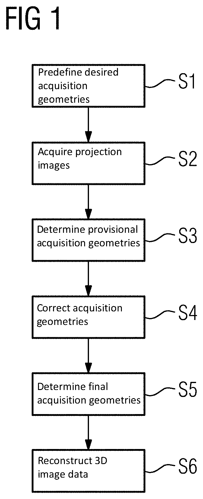
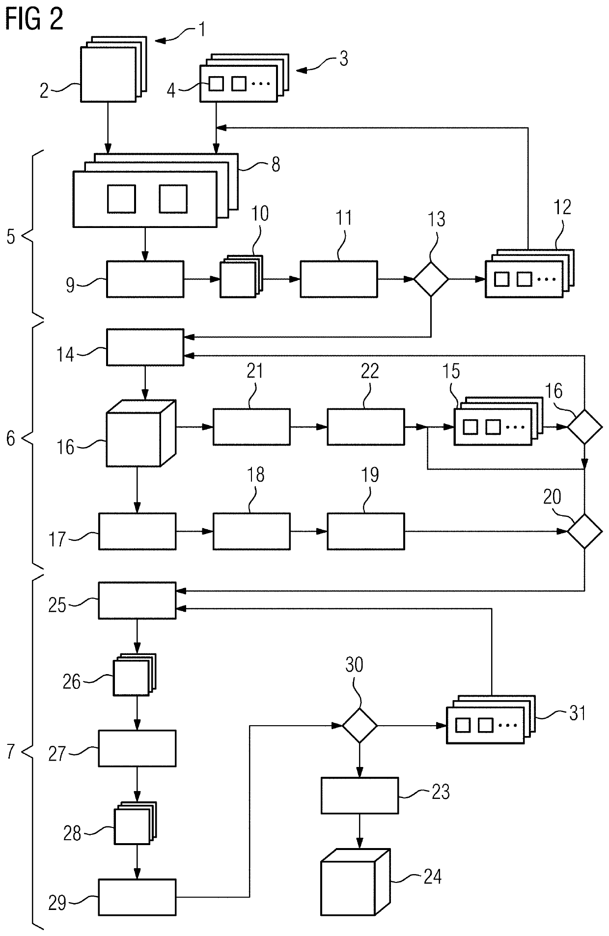
[0059]FIG. 1 depicts an exemplary embodiment of a method for determining corrected acquisition geometries of projection images of a projection image dataset or for reconstructing three-dimensional image data from these projection images. In the preparatory acts S1 and S2, a projection image dataset is provided which includes a plurality of projection images of an object under examination that have been acquired in different acquisition geometries by an acquisition device.

[0060]For this purpose, desired acquisition geometries to be used in act S1 are predefined, e.g., as part of examination planning. If, for example, a C-arm X-ray device is used to acquire the projection images, in this act, a motion sequence for the C-arm supporting the X-ray source and the X-ray detector, (e.g., a trajectory for the X-ray detector used as an acquisition device), may be predefined. The points in this motion or trajectory at which projection images are to be acquired may also be predefined. Here, it ...


PUM


Abstract

A method is provided for determining corrected acquisition geometries of projection images. The method includes providing a projection image dataset that has a plurality of projection images of an object under examination acquired by an acquisition device in different acquisition geometries. The method further includes determining a provisional acquisition geometry for each of the projection images by a first optimization method by minimizing a first cost function by varying the provisional acquisition geometry, wherein the first cost function is contingent on a plurality of consistency measures determined based on the provisional acquisition geometry for a respective pair of projection images. The method further includes determining the respective corrected acquisition geometry for each of the projection images by a second optimization method by minimizing a second cost function by varying the corrected acquisition geometries, wherein the second cost function is contingent on a measure for an image quality of image data reconstructed based on the projection images and the corrected acquisition geometries, and wherein, in a first iteration act of the second optimization method, the provisional acquisition geometries determined by the first optimization method are used as corrected acquisition geometries.

Description

[0001]The present patent document claims the benefit of European Patent Application No. 19161295.1, filed Mar. 7, 2019, which is hereby incorporated by reference.TECHNICAL FIELD[0002]The disclosure relates to a method for determining corrected acquisition geometries of projection images. The disclosure also relates to a processing device, a computer program, and a computer-readable medium.BACKGROUND[0003]Particularly in the field of medical imaging, methods are used in which a plurality of projection images are acquired in order to reconstruct three-dimensional image data from them. For example, x-ray based three-dimensional imaging is used as an important source of data in the context of medical diagnostics. In order to generate sufficient data for a representation that is as accurate as possible, an acquisition device, (e.g., an X-ray detector with an associated x-ray source), is moved around an object under examination on a circular, circular-segment-shaped, or spiral trajectory....

Claims


Application Information

Patent Timeline
Patent Type & Authority Applications(United States)
IPC IPC(8): G06T11/00G06T7/00
CPCG06T7/0012G06T2207/10116G06T11/005G06T2211/424G06N3/08G06T2207/30168G06N3/045G06T5/80
Inventor KAETHNER, CHRISTIANMANHART, MICHAELPREUHS, ALEXANDERKOWARSCHIK, MARKUS
Owner SIEMENS HEALTHCARE GMBH
Learn More