Offset coupling

a coupling and offset technology, applied in the field of couplings, can solve the problems that the two connected rotating shafts are not allowed to produce eccentricity and declination, and achieve the effect of large offs

Active Publication Date: 2020-09-17
LEE FU HSIUNG
View PDF0 Cites 1 Cited by
  • Summary
  • Abstract
  • Description
  • Claims
  • Application Information

AI Technical Summary

Benefits of technology

[0006]Thereby, in the offset coupling in the embodiments of the instant disclosure, the first coupling disc and the second coupling disc may be respectively connected to rotating shafts of two mechanical devices (such as motors or screws), and through design of the multi-link structure between the first coupling disc and the second coupling disc, the two rotating shafts of the mechanical device can allow a relatively large offset and can still keep synchronous operation in a deviation process.

Problems solved by technology

Taking the most common rigid couplings and flexible couplings as an example, the rigid couplings can allow the two connected rotating shafts to be fixed to form an integrity and accurately transmit torque, but the two connected rotating shafts are not allowed to produce eccentricity and declination.

Method used


Image

  • Offset coupling
  • Offset coupling
  • Offset coupling

Examples


Embodiment Construction

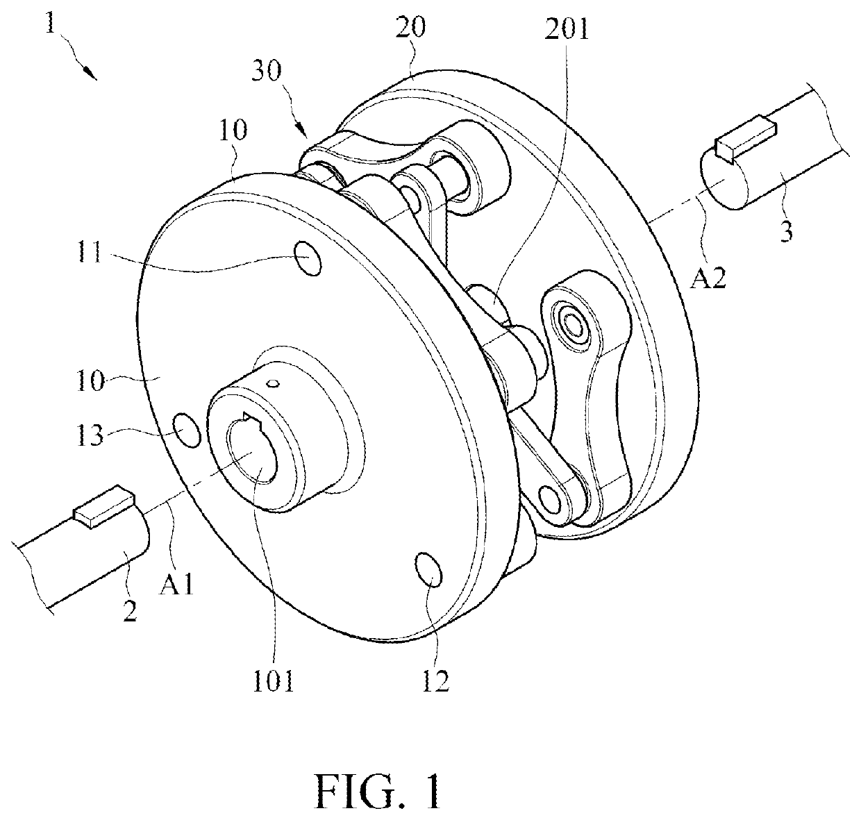
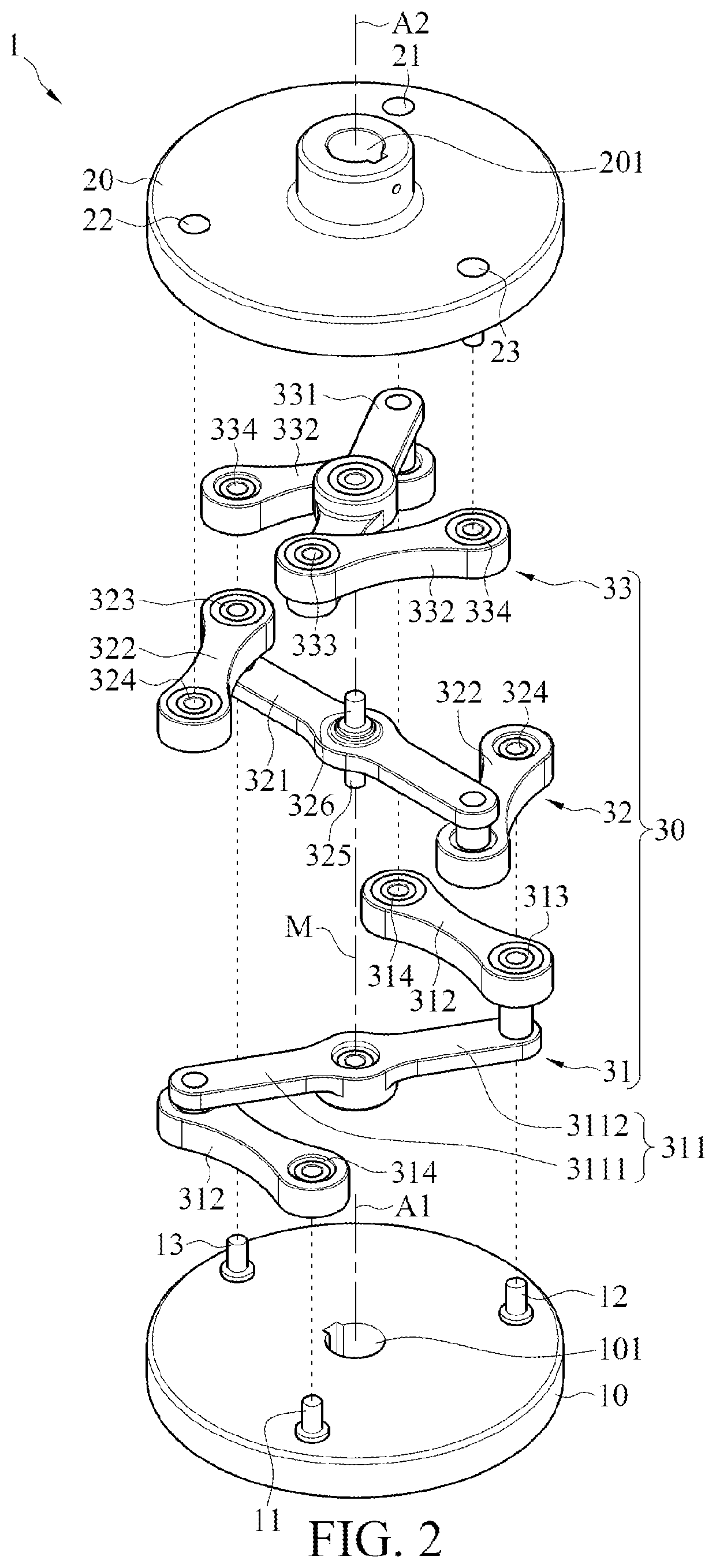
[0014]FIG. 1 is a three-dimensional diagram of an embodiment of an offset coupling according to the instant disclosure; and FIG. 2 is an exploded three-dimensional diagram of an embodiment of an offset coupling according to the instant disclosure. As shown in FIG. 1, an offset coupling 1 in this embodiment includes a first coupling disc 10, a second coupling disc 20, and a multi-link structure 30. The multi-link structure 30 is connected between the first coupling disc 10 and the second coupling disc 20. The offset coupling 1 is a power transmission component and is used to connect rotating shafts of two mechanical devices (such as motors or screws), so that the two mechanical devices can perform transmission through the offset coupling 1 and can allow an offset of a certain degree.

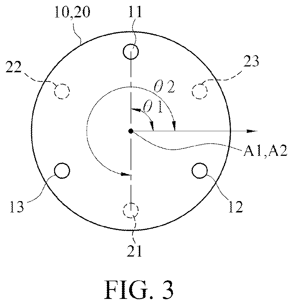
[0015]As shown in FIG. 1 and FIG. 2, the first coupling disc 10 in this embodiment is a round disc body. The first coupling disc 10 includes a first central axis A1 and at least three pivoting portions (w...


PUM


Abstract

An offset coupling includes a first coupling disc, a second coupling disc, and a multi-link structure. The first coupling disc includes a first pivoting portion, a second pivoting portion, and a third pivoting portion surround a first central axis. The second coupling disc includes a fourth pivoting portion, a fifth pivoting portion, and a sixth pivoting portion surround a second central axis. The multi-link structure includes a first linkage group, a second linkage group, and a third linkage group, two first cranks of the first linkage group are respectively pivotally connected to the first pivoting portion and the fourth pivoting portion, two second cranks of the second linkage group are respectively pivotally connected to the second pivoting portion and the fifth pivoting portion, and two third cranks of the third linkage group are respectively pivotally connected to the third pivoting portion and the sixth pivoting portion.

Description

CROSS-REFERENCE TO RELATED APPLICATION[0001]This non-provisional application claims priority under 35 U.S.C. § 119(a) to patent application Ser. No. 10 / 810,8101 in Taiwan, R.O.C. on Mar. 11, 2019, the entire contents of which are hereby incorporated by reference.BACKGROUNDTechnical Field[0002]The instant disclosure relates to a coupling, and in particular, to an offset coupling.Related Art[0003]Couplings are very common power transmission components, are mainly used to connect rotating shafts of two mechanical devices (such as motors or screws), and can be disassembled at any time when replacement or repair is required. Couplings have a long history of development. In order to meet needs of various uses, various types of couplings or couplings with various performance have been developed on the market.[0004]Taking the most common rigid couplings and flexible couplings as an example, the rigid couplings can allow the two connected rotating shafts to be fixed to form an integrity and ...

Claims


Application Information

Patent Timeline
Patent Type & Authority Applications(United States)
IPC IPC(8): F16D3/04
CPCF16D3/04F16D3/72F16D3/60
Inventor LEE, FU-HSIUNG
Owner LEE FU HSIUNG
Why Eureka
Try Eureka