Lidar device for optically detecting a field of view

a technology of optical detection and lidar device, which is applied in the direction of measurement device, control system, instruments, etc., can solve the problem of current variable representing the motor current exceeding the limit value, and achieve the effect of ensuring the safety of the eye of the lidar device, rapid detection, and cost-effectiveness

Active Publication Date: 2020-09-17
ROBERT BOSCH GMBH
View PDF4 Cites 0 Cited by
  • Summary
  • Abstract
  • Description
  • Claims
  • Application Information

AI Technical Summary

Benefits of technology

[0011]The advantage of the present invention is that the eye safety of the LIDAR device may be ensured. For example, in the case of a jamming of the electric motor, the rotation of the rotor about the rotational axis would be suppressed. In such a case, the pulsed light source would also no longer be moved. The light radiation would be emitted only along one spatial direction. The power of the emitted light radiation along this spatial direction would therefore exceed, for example, a limiting value, at which damage to an eye may occur. Multiple light pulses could impact the eye within a short time. Due to the suppression of the emission of the light radiation, according to the present invention, depending on a behavior of a current variable representing the motor current, it may now be ensured that multiple pulses of the light radiation do not impact an eye of a person in the surroundings of the LIDAR device within a short time.
[0012]In one advantageous embodiment of the present invention, it is provided that the LIDAR device continues to include at least one current sensor for detecting the behavior of the current variable representing the motor current, and a unit for comparing the behavior of the current variable representing the motor current to a predefined behavior. The control unit is also designed for emitting a suppression signal to the at least one switching means depending on the comparison.
[0013]The predefinable behavior in this case is a predefinable behavior of the current variable representing the motor current. The predefinable behavior may be a limiting value. During a continuous rotation of the rotor, the current variable representing the motor current may be constant. This may be understood to mean that, during a continuous rotation of the rotor, a very low or hardly any motor current is detectable. The detected current variable representing the motor current may have a low absolute value in this case. The detected current variable representing the motor current may be nearly zero in this case. If a jamming of the electric motor occurs, the current variable representing the motor current may increase. The increase of the current variable representing the motor current may be very rapid within a short time. If a jamming of the electric motor occurs, a comparison of the behavior of the current variable representing the motor current to a predefinable behavior may yield the result that the current variable representing the motor current exceeds a limiting value.
[0014]An advantage of this example embodiment is that the behavior of the current variable representing the motor current is detectable with the aid of few additional components of the LIDAR device. The LIDAR device is therefore kept simple and cost-effective. With the aid of the current sensor, the behavior of the current variable representing the motor current may be quickly detected. As a result, the suppression of the emission of the light radiation may take place quickly.
[0015]The predefinable behavior of the current variable representing the motor current may be stored in the control unit. The limiting value may be stored as a constant in the control unit.
[0016]In one further advantageous embodiment of the present invention, it is provided that the control unit is also designed for ascertaining the predefinable behavior of the current variable representing the motor current. For this purpose, the control unit may detect and store the profile of the behavior of the current variable representing the motor current across multiple rotations of the rotor. The control unit may detect and store the profile of the phase currents across multiple rotations of the rotor. The setpoint profile of the behavior of the current variable representing the motor current identified as the norm may be stored as a predefinable behavior.

Problems solved by technology

If a jamming of the electric motor occurs, a comparison of the behavior of the current variable representing the motor current to a predefinable behavior may yield the result that the current variable representing the motor current exceeds a limiting value.

Method used


Image

  • Lidar device for optically detecting a field of view
  • Lidar device for optically detecting a field of view
  • Lidar device for optically detecting a field of view

Examples


Embodiment Construction

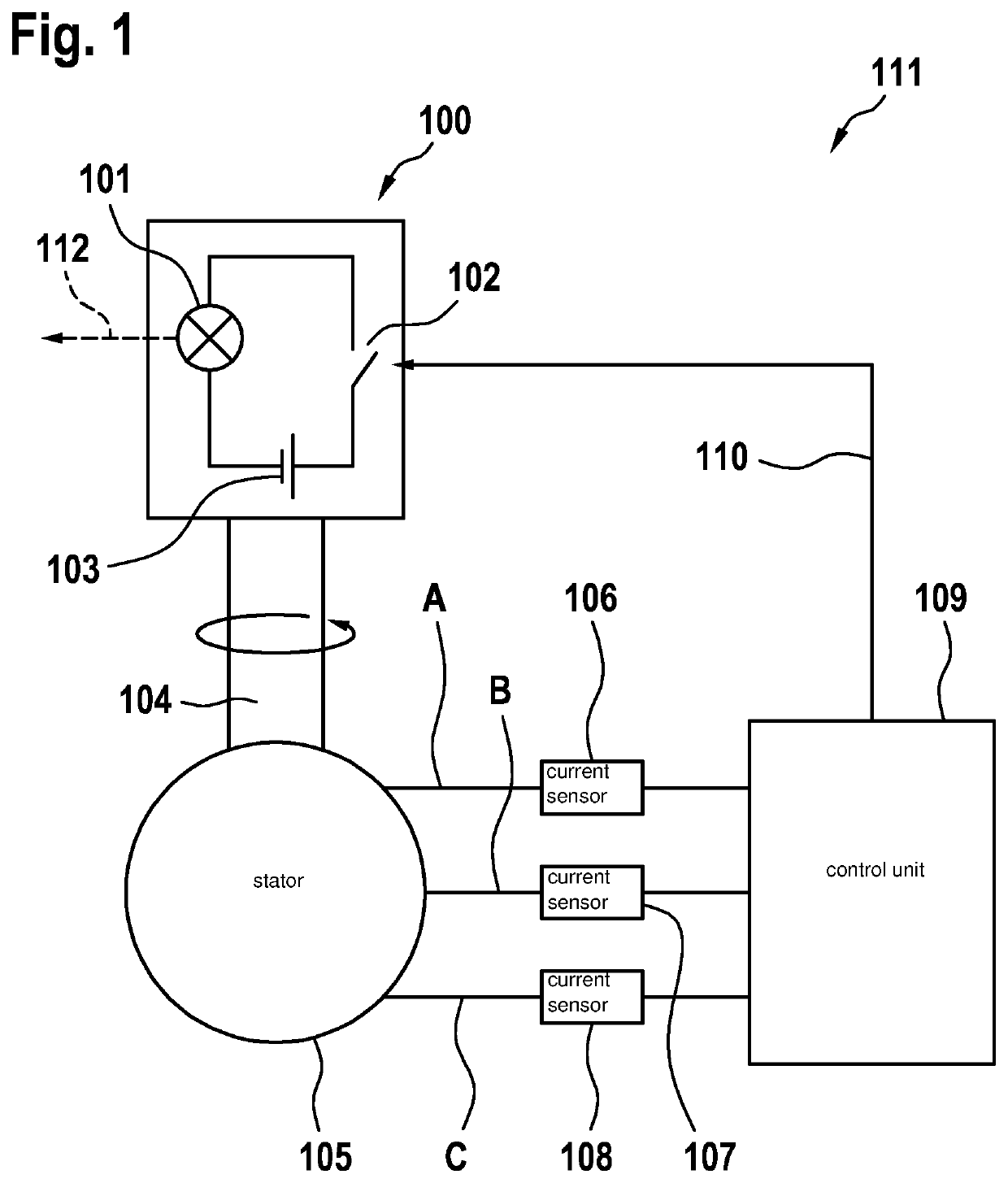
[0043]FIG. 1 shows a LIDAR device 111. LIDAR device 111 includes an electric motor. The electric motor is made up of stator 105 and rotor 100. The electric motor may be, in particular, a brushless DC motor. The electric motor may be designed as an external rotor or as an internal rotor. The electric motor may be implemented having a sensor-controlled or sensorless commutation. Rotor 100 is rotatable about a rotational axis 104. The rotation / rotary motion of the electric motor is effectuated by attractive forces and repulsive forces, which apply multiple magnetic fields onto one another. For this purpose, either stator 105 or rotor 100, or both stator 105 as well as rotor 100 include electric coils. In particular, at least three electric coils may be situated at stator 105 and / or at rotor 100. If a current flows through each of the electric coils, the electric coils generate a magnetic field, whose orientation depends on the current direction. With the aid of a predefined polarity re...


PUM


Abstract

A LIDAR device for optically detecting a field of view. The LIDAR device includes: a control unit for emitting at least one control signal; an electric motor, which has a motor current and is controllably rotatable about a rotational axis with the aid of the at least one control signal, and on which a switchable light source emitting light radiation is situated. The LIDAR device also includes at least one switch for suppressing the emission of the light radiation depending on a behavior of a current variable representing the motor current.

Description

FIELD[0001]The present invention relates to a LIDAR device for optically detecting a field of view, a working device, and a method for activating a LIDAR device.BACKGROUND INFORMATION[0002]LIDAR (Light Detection and Ranging) systems are described in the related art, in which the necessary optical elements as well as the laser and the detector are fitted on a rotor. For example, European Patent No. EP 2388615 describes a LIDAR-based, 3D point cloud measuring system including a base, a housing, and a plurality of photon transmitters and photon detectors in the housing. A rotary motor rotates the housing about the base, a communication component permitting the transmission of signals of the photon detectors to external components. In order to ensure eye safety, a control component may also be present, which suppresses the photon transmitters from transmitting photons before a desired, minimum rotational speed has been reached.BACKGROUND INFORMATION[0003]The present invention is directe...

Claims


Application Information

Patent Timeline
Patent Type & Authority Applications(United States)
IPC IPC(8): G01S17/931G01S7/481
CPCG01S17/931G01S7/4814G01S7/4817G01S7/497H02P29/027
Inventor UTERMOEHLEN, FABIANSPARBERT, JANHAS, REMIGIUSLEIDICH, STEFAN
Owner ROBERT BOSCH GMBH
Why Eureka
Try Eureka