Ultrasound probe

a technology of ultrasound probes and probes, applied in the field of ultrasound probes, can solve the problems of significant design problems such as how to improve ultrasound image quality, and achieve the effects of improving ultrasound image quality, improving dark details in ultrasound images, and increasing the number of characteristic points in ultrasound images

Inactive Publication Date: 2020-10-08
QUISDA CORP
View PDF0 Cites 1 Cited by
  • Summary
  • Abstract
  • Description
  • Claims
  • Application Information

AI Technical Summary

Benefits of technology

[0006]As mentioned in the above, the invention uses PMMA or PO to be the material of the first matching layer. When the ultrasound probe of the invention is performing ultrasound scanning, the number of characteristic points in the ultrasound image obviously increases. Accordingly, the invention can improve dark details in the ultrasound image, so as to improve ultrasound image quality effectively.

Problems solved by technology

Therefore, how to improve ultrasound image quality has become a significant design issue.

Method used


Image

  • Ultrasound probe
  • Ultrasound probe

Examples


Embodiment Construction

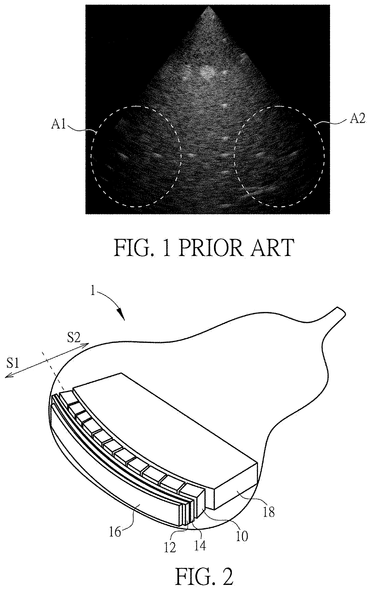
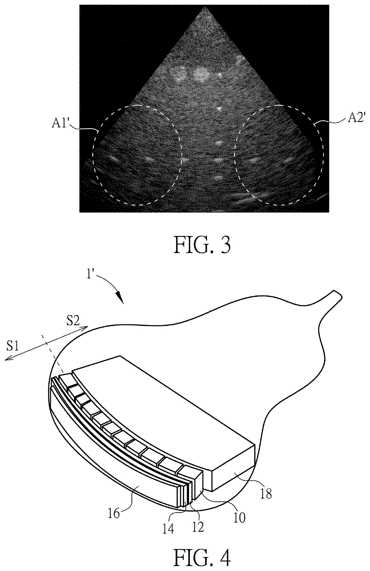
[0012]Referring to FIG. 2, FIG. 2 is a schematic diagram illustrating an ultrasound probe 1 according to an embodiment of the invention. As shown in FIG. 2, the ultrasound probe 1 comprises a transducer layer 10, a first matching layer 12, a second matching layer 14, a lens layer 16, and a backing layer 18. In this embodiment, the ultrasound probe 1 may be, but not limited to, a phased array ultrasound probe. The first matching layer 12, the second matching layer 14, and the lens layer 16 are disposed at a first side S1 of the transducer layer 10, and the backing layer 18 is disposed at a second side S2 of the transducer layer 10, wherein the first side S1 is opposite to the second side S2.

[0013]The invention may use a piezoelectric material to manufacture the transducer layer 10 first. Then, an epoxy resin is coated and cured on the first side S1 of the transducer layer 10 to form the second matching layer 14. In other words, a material of the second matching layer 14 is epoxy resi...


PUM


Abstract

An ultrasound probe includes a transducer layer, a first matching layer, a lens layer, and a backing layer. The first matching layer is disposed at a first side of the transducer layer and a material of the first matching layer is PMMA or PO. The lens layer is disposed at the first side of the transducer layer and the first matching layer is located between the transducer layer and the lens layer. The backing layer is disposed at a second side of the transducer layer, wherein the first side is opposite to the second side.

Description

BACKGROUND OF THE INVENTION1. Field of the Invention[0001]The invention relates to an ultrasound probe and, more particularly, to an ultrasound probe capable of improving ultrasound image quality effectively.2. Description of the Prior Art[0002]Since ultrasound scanning equipment does not destroy material structure and cell, the ultrasound scanning equipment is in widespread use for the field of material and clinical diagnosis. In the prior art, the process of manufacturing an ultrasound probe comprises the following steps. First, an epoxy resin is coated and cured on a side of a piezoelectric material to form a matching layer. Then, a glue is poured and cured on another side of the piezoelectric material to form a backing layer. Then, a silicone is poured and cured on the epoxy resin to form a lens layer.[0003]Referring to FIG. 1, FIG. 1 is a schematic diagram illustrating an ultrasound image scanned by an ultrasound probe of the prior art. As shown in FIG. 1, when the ultrasound p...

Claims


Application Information

Patent Timeline
Patent Type & Authority Applications(United States)
IPC IPC(8): A61B8/00B06B1/06
CPCA61B8/4444A61B8/4494A61B8/4488B06B1/067B06B2201/76G10K11/02A61B8/4455
Inventor LEE, HSUN-PIN
Owner QUISDA CORP
Why Eureka
Try Eureka