
High-efficiency heat sink

Inactive Publication Date: 2020-10-15
HUANG TSUNG HSIEN YUAN SHAN HSIANG
View PDF0 Cites 1 Cited by
  • Summary
  • Abstract
  • Description
  • Claims
  • Application Information

AI Technical Summary

Benefits of technology

The present invention aims to provide a heat sink with high efficiency that can improve heat dissipation. The invention achieves this by reducing the distance between adjacent heat sink fins on a base, allowing for a denser arrangement. The folded portion of the heat sink fin is formed by folding after being pressed and thinned, resulting in a thinner thickness. This reduces the distance between adjacent heat sink fins on the base, leading to better heat dissipation.

Problems solved by technology

Therefore, the clamping effect is not good and it is not easy to ensure its stable combination.
The heat sink fins may have different heights, and the heat sink fins are prone to shaking or falling.
The thickness of the foot of the heat sink fin, embedded in the groove of the base, is twice the thickness of the heat sink fin, which seriously restricts the distance between two adjacent heat sink fins on the base.
The heat sink fins cannot be arranged densely, which will affect the heat dissipation effect of the entire heat sink.

Method used


Image

  • High-efficiency heat sink
  • High-efficiency heat sink
  • High-efficiency heat sink

Examples


Embodiment Construction

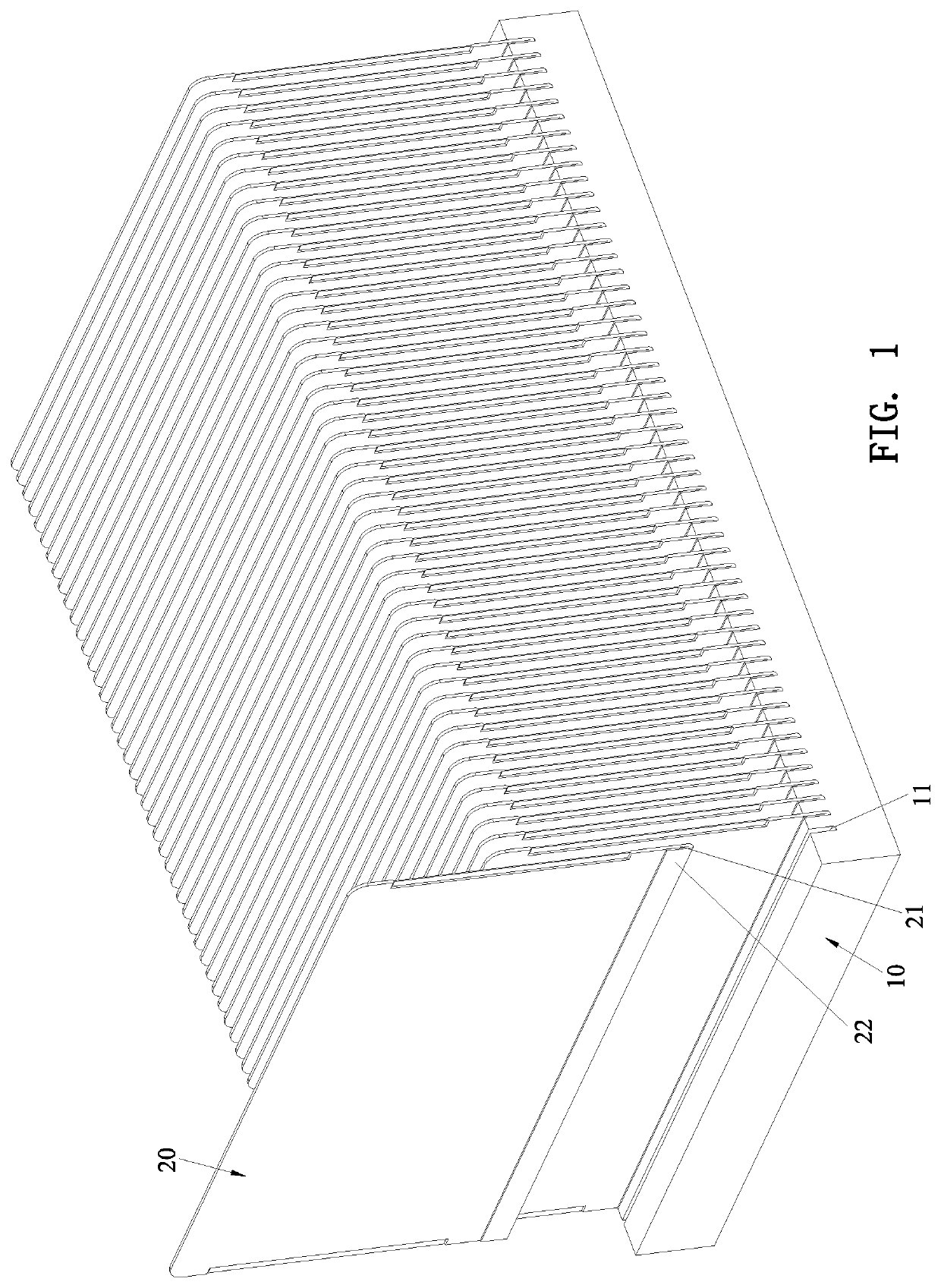
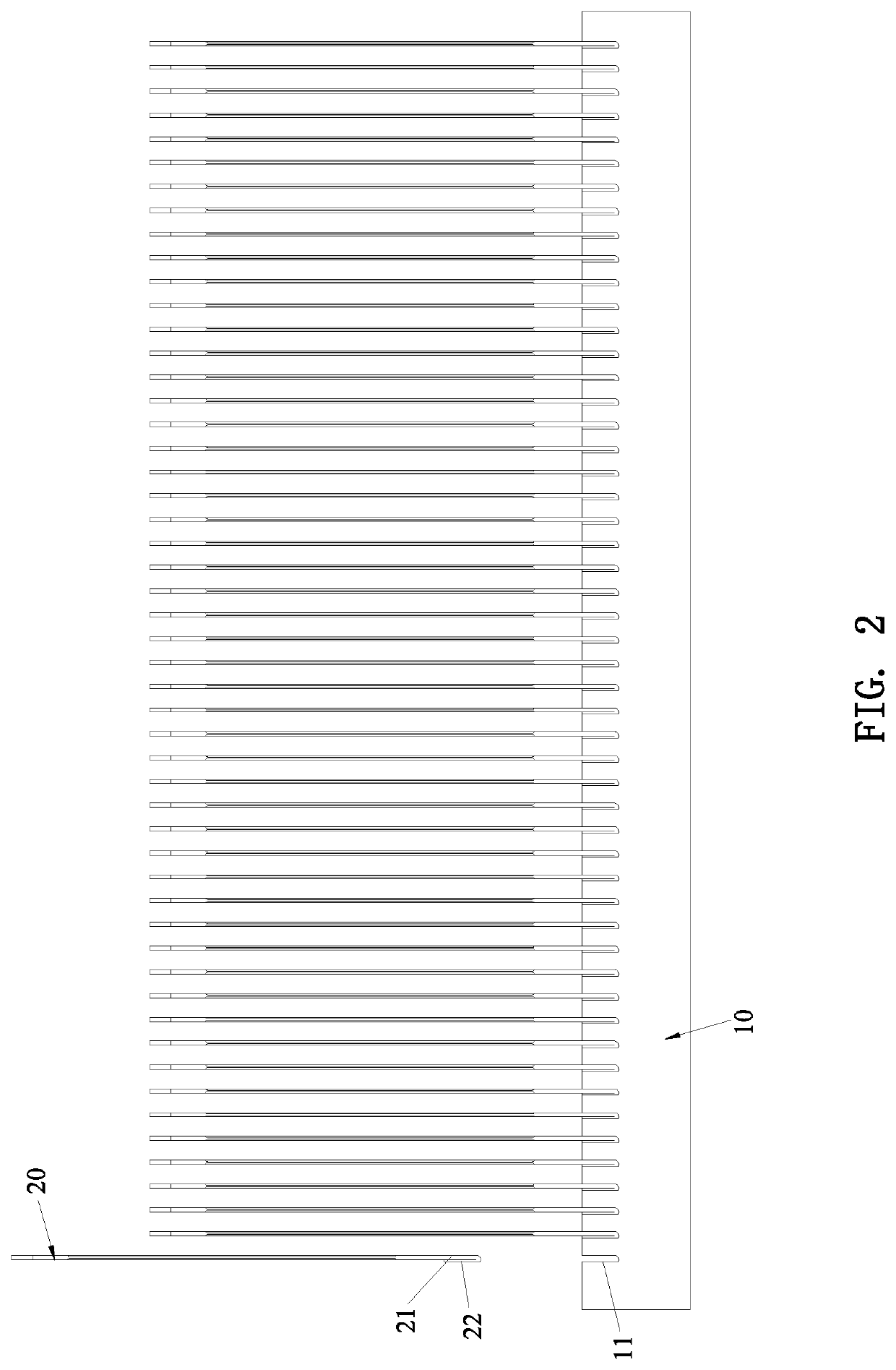
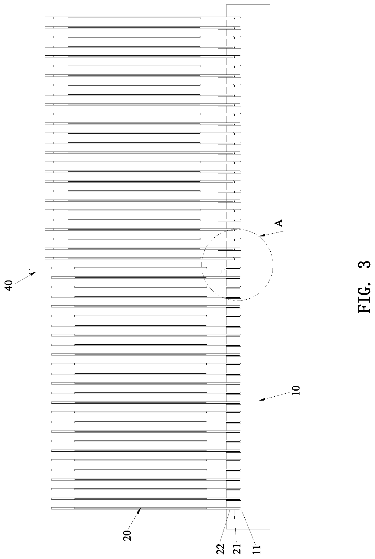
[0036]Referring to FIG. 1 through FIG. 18, a specific structure in accordance with a preferred embodiment of the present invention is shown, comprising a base 10 and a plurality of heat sink fins 20.

[0037]The surface of the base 10 is formed with a plurality of spaced grooves 11 for attachment of the heat sink fins 20.

[0038]An insertion end 21 of each heat sink fin 20 is reversely folded and extends to form a folded portion 22. The folded portion 22 is formed by folding after being pressed and thinned. The thickness of the folded portion 22 is less than the thickness of the insertion end 21. The folded portion 22 and the insertion end 21 are fitted and embedded into a corresponding one of the grooves 11 of the base 10.

[0039]Through the base 10 and the plurality of heat sink fins 20, after the folded portion 22 of each heat sink fin 20 is inserted into the corresponding groove 11 of the base 10, a press head 40 is aligned with the folded portion 22 for pressing. The press head 40 cov...


PUM

PropertyMeasurementUnit
Thicknessaaaaaaaaaa
Efficiencyaaaaaaaaaa
Distanceaaaaaaaaaa

Abstract

A high-efficiency heat sink includes a base and a plurality of heat sink fins A folded portion of each heat sink fin is formed by folding after being pressed and thinned, so that the thickness of the folded portion is less than the thickness of an insertion end of each heat sink fin. The thickness of the portion where the heat sink fin is inserted into a groove of the base is less than twice the thickness of the heat sink fin. It is beneficial to reduce the distance between two adjacent heat sink fins on the base, so that the heat sink fins can be arranged more densely, thereby improving the heat dissipation effect of the entire heat sink effectively.

Description

BACKGROUND OF THE INVENTION1. Field of the Invention[0001]The present invention relates to a heat sink, and more particularly to a high-efficiency heat sink.2. Description of the Prior Art[0002]The heat sink fins and the base of a conventional heat sink are assembled together by soldering or by pressing. The heat sink fins are first inserted in the preset grooves or the clamping base, and then pressed by a press head so that the heat sink fins are clamped and combined with the grooves of the base. For example, as disclosed in U.S. Pat. No. 5,014,776, the respective two side walls of the grooves are pressed to cause a deformation to clamp the heat sink fins, such that the heat sink fins and the base are assembled together. In the above patent, through the deformation of both sides of the groove, the foot of the heat sink fin is clamped. However, the clamping force is concentrated on the deformation positions on both sides of the opening of the groove, only having two point-like clamp...

Claims


Application Information

Patent Timeline
IPC IPC(8): F28F3/06B21D53/02
CPCF28F3/06F28F2275/125B21D53/022F28F2215/00B21D39/038F28D15/0233F28D15/0275F28D2021/0029F28F2275/122
Inventor HUANG, TSUNG-HSIEN
Owner HUANG TSUNG HSIEN YUAN SHAN HSIANG
Learn More