Eureka AIR delivers breakthrough ideas for toughest innovation challenges, trusted by R&D personnel around the world.

Display panel

Active Publication Date: 2020-10-15
AU OPTRONICS CORP
View PDF0 Cites 2 Cited by
  • Summary
  • Abstract
  • Description
  • Claims
  • Application Information

AI Technical Summary

Benefits of technology

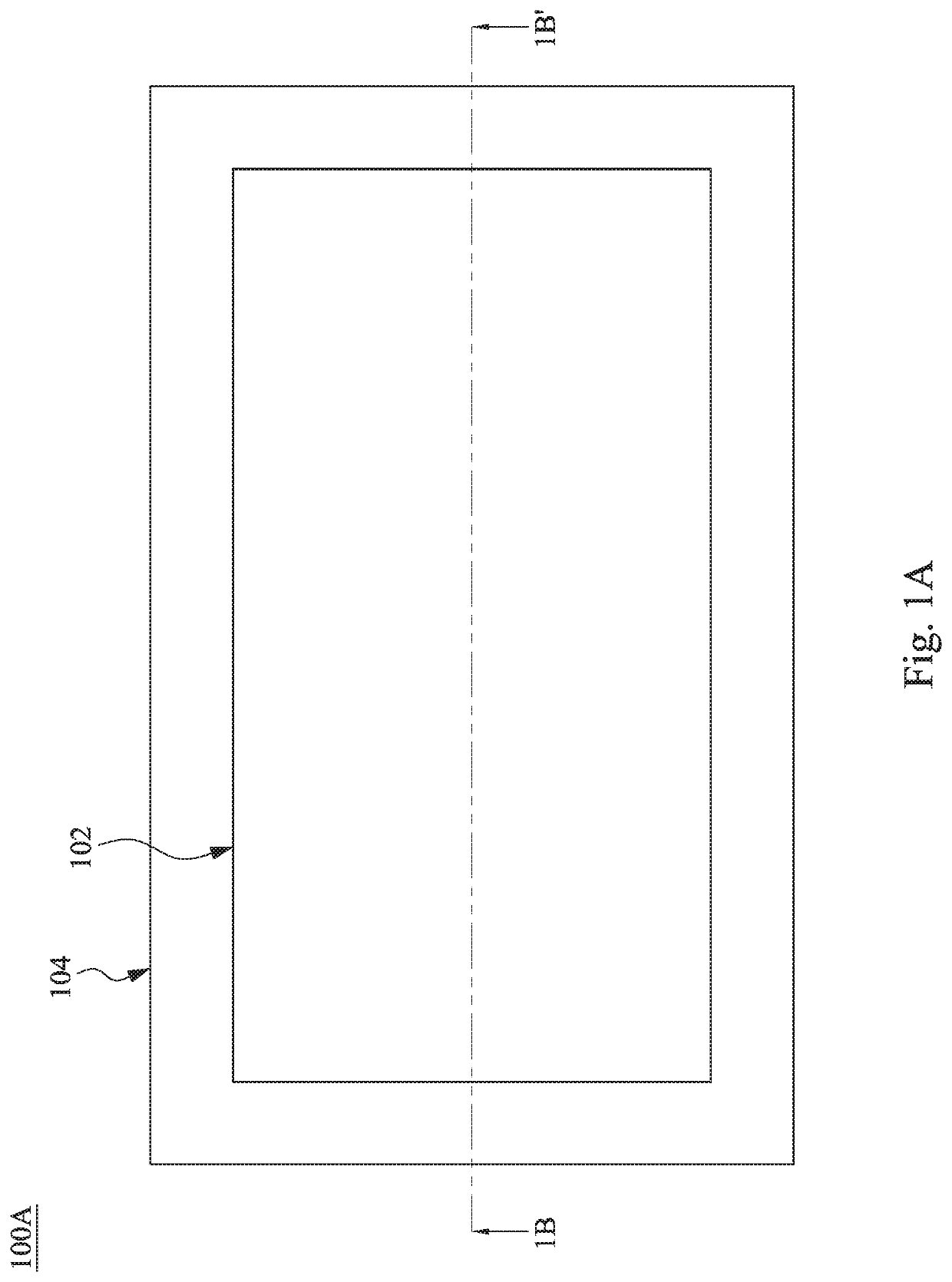
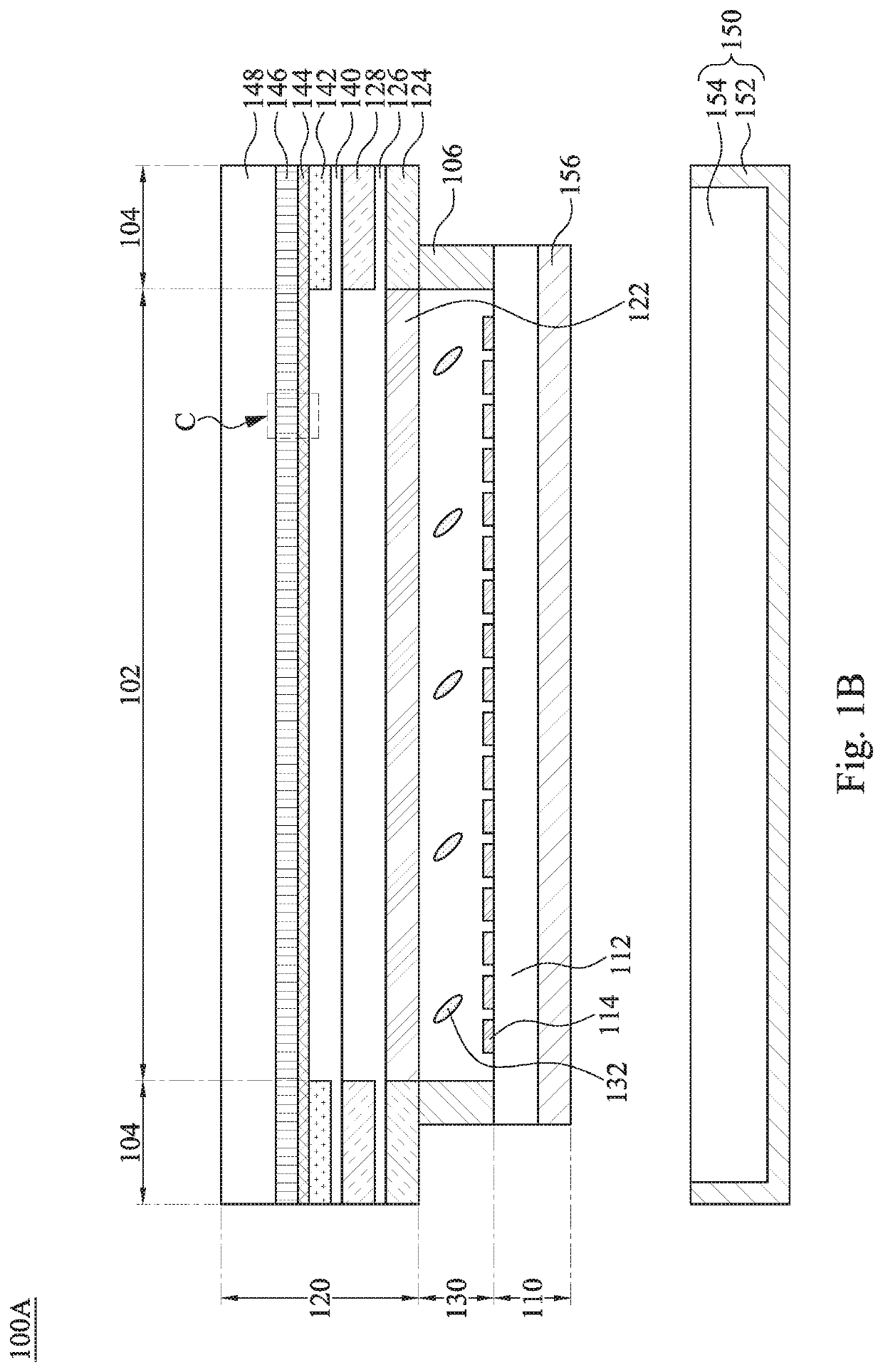
This patent describes a display panel that can switch between an image mode and a specular reflection mode. In the image mode, the display panel shows an image by controlling the display medium layer through the pixel array. In the specular reflection mode, the display panel reduces the specular reflection effect by attenuating the light beams leaving from the interior of the display panel. The technical effect of this patent is to provide a display panel that can switch between different modes for better image quality and control over the specular reflection effect.

Problems solved by technology

However, owing to the different structures of the display area and the peripheral area of the display panel, the specular reflection effects provided by them are different, which in turn causes the user experience of the customers to be affected.

Method used


Image

  • Display panel
  • Display panel
  • Display panel

Examples


Embodiment Construction

[0026]In the following detailed description, for purposes of explanation, numerous specific details are set forth in order to provide a thorough understanding of the disclosed embodiments. It will be apparent, however, that one or more embodiments may be practiced without these specific details. In other instances, well-known structures and elements are schematically depicted in order to simplify the drawings.

[0027]It will be understood that, although the terms first, second, third etc. may be used herein to describe various elements, components, areas, regions, layers and / or sections, these elements, components, areas, regions, layers and / or sections should not be limited by these terms. These terms are only used to distinguish one element, component, area, region, layer or section from another element, component, area, region, layer or section. Thus, a first element, component, area, region, layer or section discussed below could be termed a second element, component, area, region...


PUM


Abstract

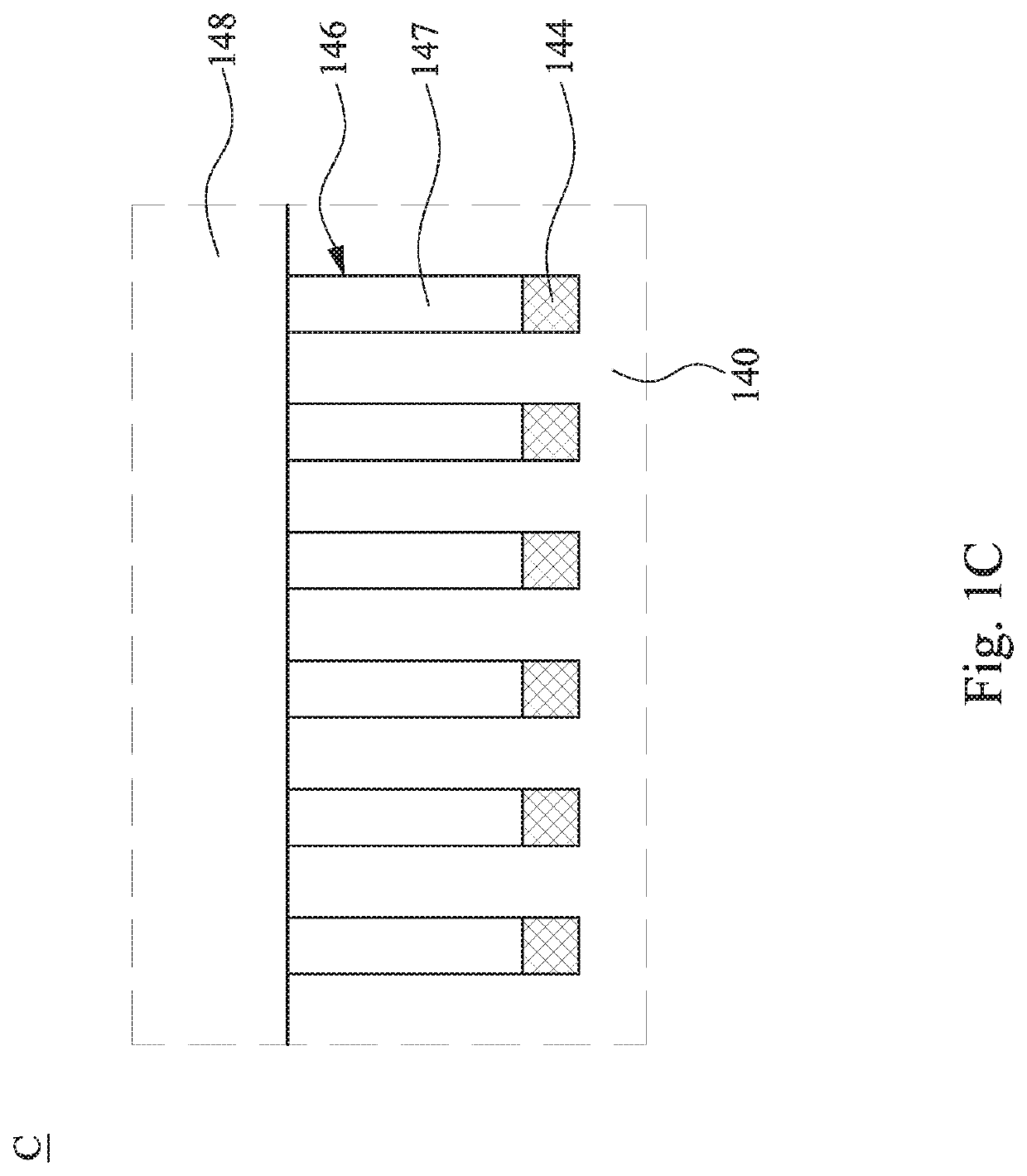
A display panel has a display area and a peripheral area. The peripheral area is located outside the display area. The display panel includes a first substrate, a second substrate, and a display medium layer. The second substrate is located above the first substrate and includes a first polarization layer, a first quarter wave plate (QWP), a reflection layer, and a pixel array. The first polarization layer is located within the display area and the peripheral area and includes a wire-grid polarizer. The first QWP is located within the peripheral area. The reflection layer is located within the peripheral area, in which the first QWP is located between the first polarization layer and the reflection layer. The pixel array is at least located within the display area. The display medium layer is located between the first substrate and the second substrate.

Description

RELATED APPLICATIONS[0001]This application claims priority to Taiwan Application Serial Number 108112549, filed Apr. 10, 2019, which is herein incorporated by reference.BACKGROUNDField of Invention[0002]The present disclosure relates to a display panel.Description of Related Art[0003]In various consumer electronic products, display panels have been widely utilized to provide images or operation menus. In this regard, with the development of science and technology, display panels have also developed into a variety of forms. For example, not only can mirror display panels provide images or operation menus, but they can also provide the mirror function to satisfy the demand of the consumers.[0004]For a mirror display panel, one piece of traditional semi lens glass is required on the display panel, and the display area and the peripheral area of the display panel are able to provide specular reflection functions. However, owing to the different structures of the display area and the per...

Claims


Application Information

Patent Timeline
IPC IPC(8): G02F1/1335H01L27/32H01L51/52
CPCG02F1/133512G02F2001/133548G02F2001/133541H01L27/3244G02F1/133528G02F1/133553G02F2203/02H01L51/5284G02F1/13363G02F1/1335G02F1/133514G09F9/33G02F1/133548G02F1/133638H10K59/8792H10K59/12G02F1/1333G02F1/13332G02F1/133331G02F1/133388H10K59/35G02F1/133541H10K50/865
Inventor NIAN, HAN-SHENGCHIA, LI-KAISHIH, YU-CHENGWANG, WEI-SYUNCHOU, SHAN-YINGHUANG, SHENG-MINGLU, JEN-KUEI
Owner AU OPTRONICS CORP
Why Eureka
Eureka Blog
Learn More