Phase predictor and associated method of use

a technology which is applied in the field of phase predictor and associated method of use, can solve the problems of complex and expensive implementation, provide the necessary accuracy required, etc., and achieve the effect of improving the accuracy of timestamp

Active Publication Date: 2020-10-15
MICROCHIP TECH INC
View PDF0 Cites 0 Cited by
  • Summary
  • Abstract
  • Description
  • Claims
  • Application Information

AI Technical Summary

Benefits of technology

[0006]In accordance with various embodiments of the present invention, an improved system and method for predicting the phase relationship between two clock signals is provided. In particular, the present invention provides a system and method that increases the accuracy and resolution of the predicted phase relationship, while also supporting different clock frequencies.
[0011]Accordingly, the present invention provides a phase predictor that provides an improved timestamp accuracy by predicting the phase relationship between two different clock signals, while also supporting different clock frequencies.

Problems solved by technology

While phase predictors are known in the art, they do not provide the necessary accuracy required for modern equipment environments, they may support only a limited number of specific clock rates and they often involve complex and expensive implementation.

Method used


Image

  • Phase predictor and associated method of use
  • Phase predictor and associated method of use
  • Phase predictor and associated method of use

Examples


second embodiment

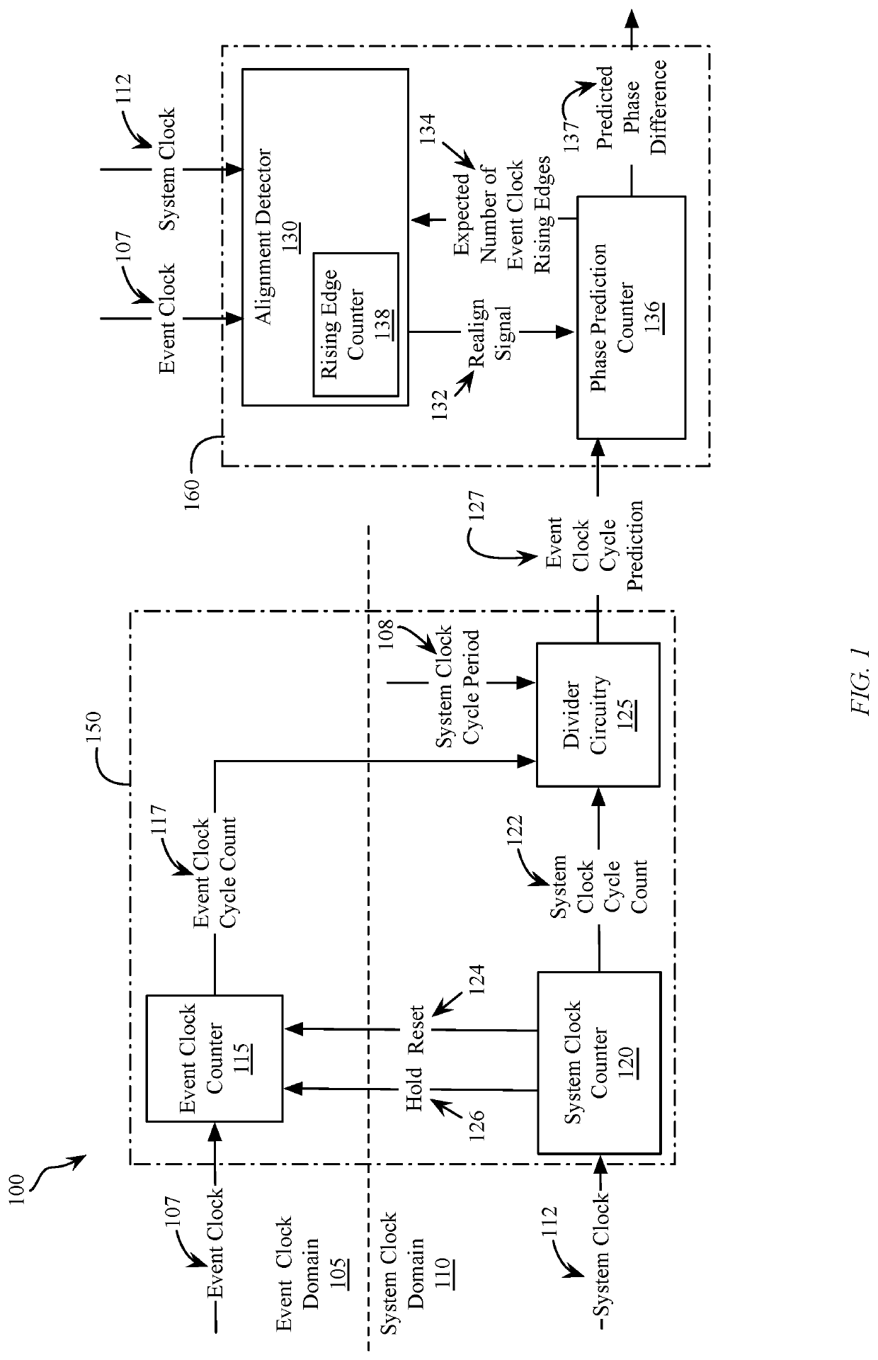
[0030]In a second embodiment, the event clock cycle prediction 127 is determined relative to one event clock cycle period and the event clock cycle prediction 127 is the time from a system clock edge to a previous system clock edge measured with a time unit equal to one cycle of event clock 107. In this embodiment, the system clock counter 120 counts cycles of system clock 112 and outputs the number of system clock cycles 122 that occur during a counted number of event clock cycles 117 counted by the event clock counter 115. The divider circuitry 125 divides the resulting system clock cycle count 122 by the event clock cycle count 117 to determine the event clock cycle prediction 127, wherein in this embodiment, the event clock cycle prediction 127 is the number of system clock cycles that occur during each cycle of event clock 107. In an exemplary embodiment, if 221 clock cycles of system clock 112 are counted by the system clock counter 120 during the time that 128 clock cycles of...

third embodiment

[0031]In a third embodiment, the event clock cycle prediction 127 is determined relative to a known system clock cycle period 108 and the event clock cycle prediction 127 is the time from an event clock edge to a previous event clock edge determined in relation to the known system clock cycle period 108, measured in time units, which in an exemplary embodiment is expressed in nanoseconds. The system clock cycle period 108 is known by the divider circuitry 125 and is a constant value. In this embodiment, the system clock counter 120 counts cycles of system clock 112 and outputs the number of system clock cycles 122 that occur during a counted number of event clock cycles 117 counted and output by the event clock counter 115. The event clock cycle prediction 127 is determined by multiplying a ratio of the number of counted system clock cycles to the number of event clock cycles by the known system clock cycle period 108. In an exemplary embodiment, given that the system clock cycle pe...

first embodiment

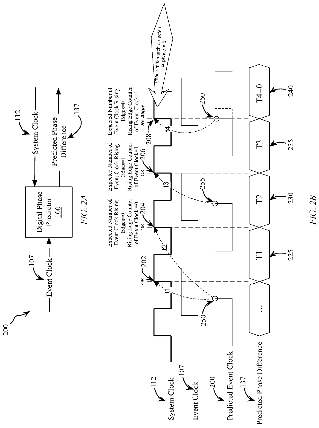
[0037]In order to accurately predict the phase difference 137 between the system clock 112 and the event clock 107, a predicted event clock 200 is emulated by the phase prediction counter 136 within the system clock domain 110 that is based upon the event clock cycle prediction 127 determined by the event clock cycle predictor 150. In accordance with the first embodiment previously described the phase prediction counter 136 is incremented with the latest event clock cycle prediction 127 every system clock cycle. If the value of the incremented phase prediction counter 136 becomes larger than “1”, representing one event clock period, the value is divided by one and the value is set to the modulo value and the quotient of the division remains representing the expected number of event clock rising edges 134. The predicted event clock 200 is not a physical clock signal but is instead an emulated clock signal, represented by a predicted phase value, in which it is desired to know a phase...


PUM


Abstract

A phase predictor to accurately detect and predict the phase relationship between two clocks running at different frequencies. The phase relationship can be used to record the transmission and reception times of Ethernet frames transmitted over a transmission medium with very high accuracy.

Description

CROSS-REFERENCE TO RELATED APPLICATIONS[0001]This application claims priority to currently pending U.S. Provisional Patent Application No. 62 / 833,533, filed on Apr. 12, 2012 entitled, “Digital Clock Phase Detector and Associated Method of Use”, which is hereby incorporated by reference in its entirety.BACKGROUND OF THE INVENTION[0002]Phase predictors are known to continuously predict the phase relationship between two different clocks. Knowing the phase relationship between two different clocks has application in digital phase locked loops (PLLs) and Precision Time Protocol (PTP) systems, as well as 5G telecom networks and various equipment measurement systems where it is necessary to know the phase relationship of the clocks to an accuracy that provides for synchronization of the clock signals.[0003]The synchronization accuracy of equipment operating in two different clock domains depends upon the accuracy of the phase relationship predicted by the phase predictor. For example, acc...

Claims


Application Information

Patent Timeline
Patent Type & Authority Applications(United States)
IPC IPC(8): H03K5/135H03L7/085H04L7/033
CPCH03L7/085H03K5/135H04L7/033H04J3/0697H04L7/0012
Inventor TERSTRUP, MORTENJOERGENSEN, THOMAS
Owner MICROCHIP TECH INC
Why Eureka
Try Eureka