Method of manufacturing aluminum-based clad heat sink, and aluminum-based clad heat sink manufactured thereby

a technology of heat sink and aluminum clad, which is applied in the direction of layered products, basic electric elements, chemical instruments and processes, etc., can solve the problems of relatively mechanical and physical weak, and large amount of heat generated by electronic parts, so as to achieve the effect of simple process procedure and competitive advantage in pri

Active Publication Date: 2020-10-22
PUKYONG NAT UNIV IND ACADEMIC COOPERATION FOUND
View PDF0 Cites 0 Cited by
  • Summary
  • Abstract
  • Description
  • Claims
  • Application Information

AI Technical Summary

Benefits of technology

[0022]The manufacturing method according to the present invention is capable of producing a light high-strength high-conductivity aluminum-based clad heat sink having a competitive advantage in terms of price because the manufacturing method is based on direct extrusion which is suitable for mass production due to its simplicity in process procedure and equipment required.

Problems solved by technology

Generally, electronic parts generate a large amount of heat during operation thereof.
Since heat generation of such electronic parts are likely to result in malfunctioning of or damage to the electronic parts, it is required to dissipate the heat generated from the electronic parts.
Despite many advantages described above, aluminum has a problem in that it is relatively mechanically and physically weak.

Method used


Image

  • Method of manufacturing aluminum-based clad heat sink, and aluminum-based clad heat sink manufactured thereby
  • Method of manufacturing aluminum-based clad heat sink, and aluminum-based clad heat sink manufactured thereby
  • Method of manufacturing aluminum-based clad heat sink, and aluminum-based clad heat sink manufactured thereby

Examples


example 1

[0087]Carbon nanotubes (manufactured by SCSiAl headquartered in Luxembourg) having a purity of 99.5%, a diameter of 10 nm or less, and a length of 30 μm or less were used. Aluminum powder (manufactured by MetalPlayer headquartered in Korea) having an average particle size of 45 μm and a purity of 99.8% was used.

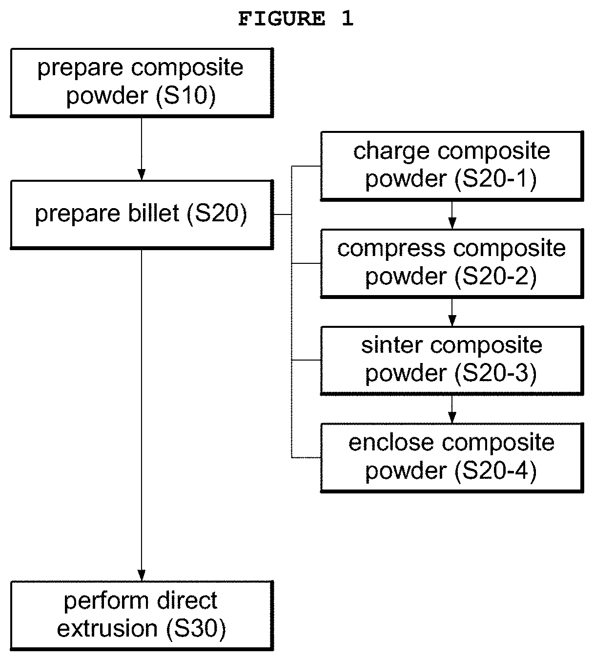
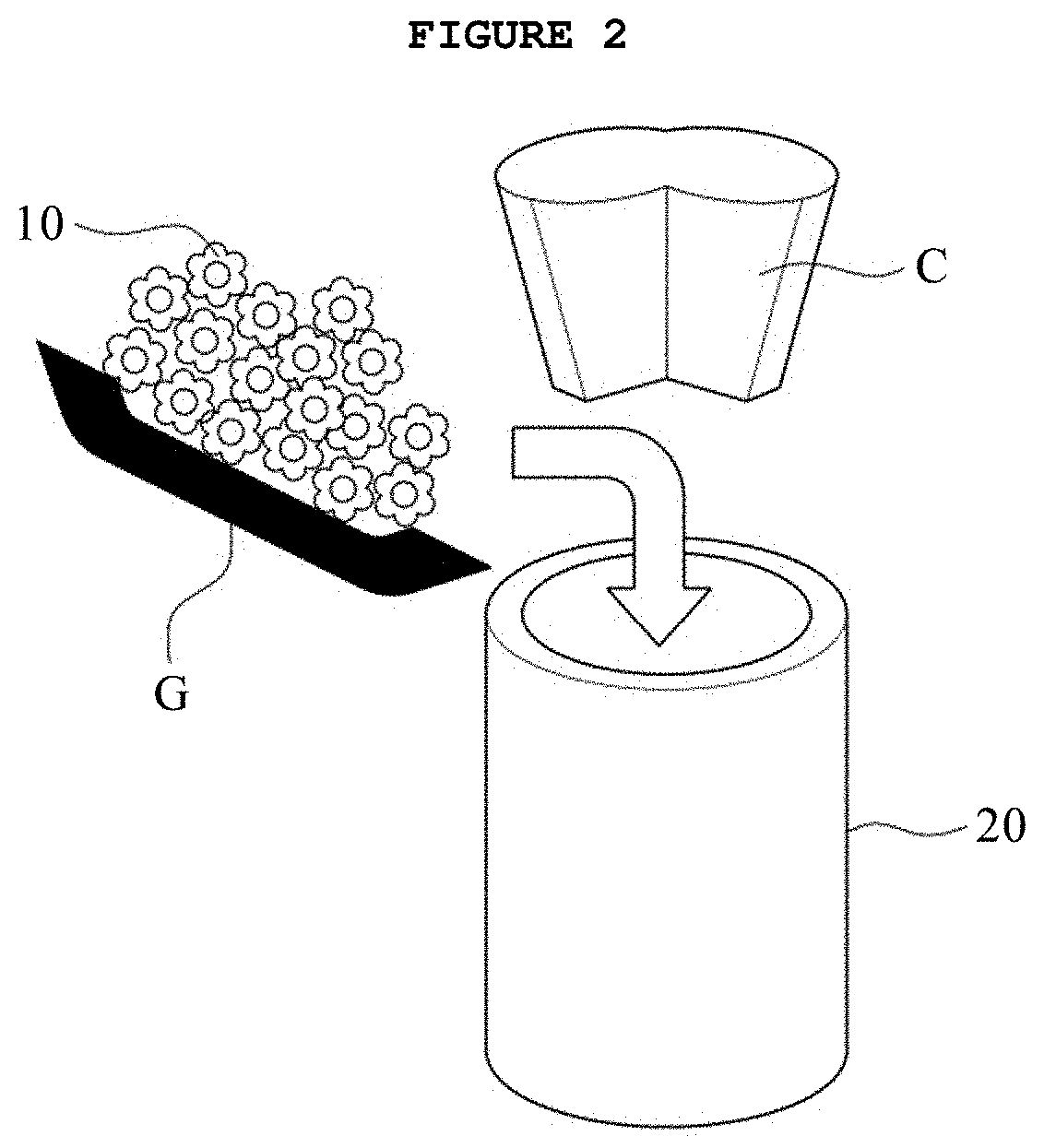
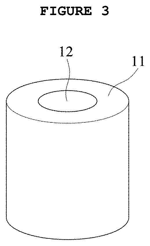
[0088]A multi-layered billet was manufactured such that a third billet having a columnar shape was positioned at the center of a metal can serving as a first billet and a second billet (composite powder) was positioned between the first billet and the third billet.

[0089]The second billet included aluminum-CNT composite powder containing 0.1 part by volume of the carbon nanotube with respect to 100 parts by volume of the aluminum powder. The first billet was made of aluminum 6063, and the third billet was made of aluminum 3003.

[0090]The second billet was manufactured in manner described below. 100 parts by volume of the aluminum powder and 0.1 parts by volume of the carbon nan...

example 2

[0093]In the same manner as in Example 1, an aluminum-CNT composite powder containing the carbon nanotubes in a content of 1 part by volume was prepared and a multi-layered billet was prepared by using the composite powder.

[0094]The prepared multi-layered billet was directly extruded under the same conditions as in Example 1 to produce an aluminum-based clad heat sink of straight fin type.

example 3

[0095]In the same manner as in Example 1, an aluminum-CNT composite powder containing the carbon nanotubes in a content of 3 parts by volume was prepared and a multi-layered billet was prepared by using the composite powder.

[0096]The prepared multi-layered billet was directly extruded under the same conditions as in Example 1 to produce an aluminum-based clad heat sink of straight fin type.


PUM

PropertyMeasurementUnit
pressureaaaaaaaaaa
temperatureaaaaaaaaaa
pressureaaaaaaaaaa

Abstract

Disclosed are a method of manufacturing an aluminum-based clad heat sink, and an aluminum-based clad heat sink manufactured by the method. The method includes ball-milling (i) aluminum or aluminum alloy powder and (ii) carbon nanotubes (CNT) to prepare a composite powder, preparing a multi-layered billet using the composite billet, and directly extruding the multi-layered billet using an extrusion die to produce a heat sink. The method has an advantage of producing a light high-strength high-conductivity aluminum-based clad heat sink having an competitive advantage in terms of price by using direct extrusion that is suitable for mass production due to its simplicity in process procedure and equipment required.

Description

CROSS REFERENCE TO RELATED APPLICATION[0001]The present application claims priority to Korean Patent Application No. 10-2019-0044421 (filed Apr. 16, 2019), the entire contents of which is incorporated herein for all purposes by this reference.1. FIELD OF THE INVENTION[0002]The present invention relates to a method of manufacturing a heat sink, and a heat sink manufactured by the method. More particularly, the present invention relates to a method of manufacturing an aluminum-based clad heat sink, and an aluminum-based clad heat sink manufactured thereby.2. DESCRIPTION OF THE RELATED ART[0003]Generally, electronic parts generate a large amount of heat during operation thereof. Since heat generation of such electronic parts are likely to result in malfunctioning of or damage to the electronic parts, it is required to dissipate the heat generated from the electronic parts. A heat sink with multiple fins is widely used as a heat dissipation device for electronic parts.[0004]Conventional...

Claims


Application Information

Patent Timeline
Patent Type & Authority Applications(United States)
IPC IPC(8): B22F3/20B22F3/105B22F7/00B22F9/04
CPCB22F7/008B22F2009/043B22F2302/403B22F2301/052B22F3/105B22F2303/40B22F9/04B22F3/20B22F1/0003B22F2003/1051B22F2998/10B22F3/02C22C1/0416C22C2026/002C22C1/05B22F2999/00B22F2207/01B22F2005/005C22C21/00B22F7/06B32B15/016B22F7/02B22F2007/042B22F7/064B22F3/1216B22F2003/208C22C26/00H01L23/3733H01L21/4871H01L23/3736C22C33/02
Inventor KWON, HANSANG
Owner PUKYONG NAT UNIV IND ACADEMIC COOPERATION FOUND
Why Eureka
Try Eureka