Electrically powered suspension system

a suspension system and electric motor technology, applied in the direction of resilient suspensions, vehicle springs, vehicle components, etc., can solve the problems of generating unusual noise around the mechanism, affecting ride comfort and steering stability, and affecting the performance of the vehicle, etc., to achieve the effect of suppressing the generated unusual nois

Active Publication Date: 2020-10-22
HONDA MOTOR CO LTD
View PDF0 Cites 3 Cited by
  • Summary
  • Abstract
  • Description
  • Claims
  • Application Information

AI Technical Summary

Benefits of technology

[0010]The present invention has been made in view of the above circumstances, and an object of the present invention is to provide an electrically powered suspension system capable of suppressing an unusual noise generated around the mechanism portion of the electromagnetic actuator when the stroke direction of the electromagnetic actuator is reversed.

Problems solved by technology

In this case, the driving force generated by the electromagnetic actuator is not transmitted properly to a sprung member and an unsprung member.
This may result in degradation in ride comfort and steering stability.
The inventors of this application have found that an unusual noise may be generated around the mechanism portion of the electromagnetic actuator in this electrically powered suspension system when a stroke direction of the electromagnetic actuator is reversed.
In particular, if the electrically powered suspension system is mounted on a relatively heavy vehicle, an unusual noise generated around the mechanism portion of the electromagnetic actuator is prone to occur noticeably because an influence of the friction force generated in the electromagnetic actuator is relatively large.
This problem has not been clearly recognized so far and thus the conventional electrically powered suspension system has not provided a solution to achieve this problem.

Method used


Image

  • Electrically powered suspension system
  • Electrically powered suspension system
  • Electrically powered suspension system

Examples


Embodiment Construction

[0031]An electrically powered suspension system according to one embodiment of the present invention will be described in detail with reference to the drawings.

[0032]In the following drawings, the same reference numeral is assigned to components each having a common function. In addition, the size and shape of a component may be schematically illustrated by being deformed or exaggerated for convenience of explanation.

11 According to One Embodiment of Present Invention>

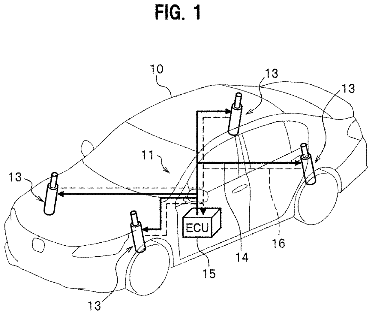
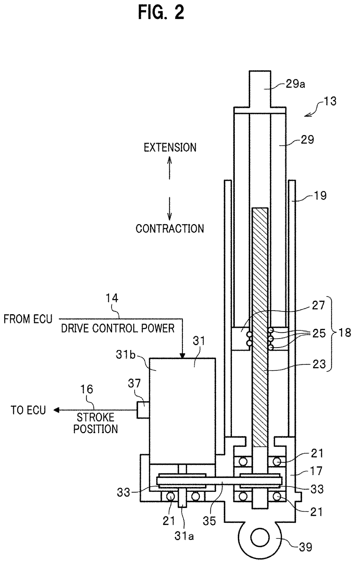
[0033]First, a basic configuration of an electrically powered suspension system 11 according to one embodiment of the present invention will be described with reference to FIGS. 1 and 2.

[0034]FIG. 1 is a diagram showing the overall configuration of an electrically powered suspension system 11 according to one embodiment of the present invention. FIG. 2 is a partially sectional view of an electromagnetic actuator 13 constituting the electrically powered suspension system 11.

[0035]As seen in FIG. 1, the electrically powe...


PUM


Abstract

An electrically powered suspension system includes: an electromagnetic actuator; an information acquisition unit configured to acquire time-series information related to stroke position of the electromagnetic actuator, information on stroke velocity, and an amount of change in stroke of the electromagnetic actuator and information on a stroke direction based on the time-series information; a damping force calculation unit configured to calculate target damping force based on the information on the stroke velocity; and a drive control unit configured to control driving of the electromagnetic actuator using target driving force obtained based on the target damping force. The damping force calculation unit calculates equivalent friction compensation force based on the amount of change in the stroke and the information on the stroke direction, and corrects the target damping force based on the calculated equivalent friction compensation force. The equivalent friction compensation force has elastic force component and dynamic friction force component.

Description

CROSS-REFERENCE TO RELATED APPLICATION[0001]This application claims the benefit of foreign priority to Japanese Patent Application No. 2019-078130, filed on Apr. 16, 2019, which is incorporated by reference in its entirety.TECHNICAL FIELD[0002]The present invention relates to an electrically powered suspension system including an electromagnetic actuator. The electromagnetic actuator is disposed in parallel with a spring member installed between a vehicle body and a wheel of a vehicle, and generates a driving force related to vibration damping of the vehicle.BACKGROUND ART[0003]An electrically powered suspension system including an electromagnetic actuator has conventionally been known. The electromagnetic actuator of this electrically powered suspension system is disposed in parallel with a spring member installed between a vehicle body and a wheel of a vehicle, and generates a driving force related to vibration damping of the vehicle using an electric motor. The electromagnetic ac...

Claims


Application Information

Patent Timeline
Patent Type & Authority Applications(United States)
IPC IPC(8): B60G17/0165B60G17/06B60G17/016B60G15/04
CPCB60G17/0162B60G2500/104B60G17/06B60G2400/204B60G2204/62B60G2206/41B60G2200/10B60G2400/40B60G2204/419B60G15/04B60G2400/82B60G17/0165B60G2800/162B60G2600/182B60G2600/73B60G2202/31B60G2202/25B60G2202/42B60G17/0157B60G13/14B60G17/0182B60G2202/442B60G2202/30B60G2500/10B60G2600/02B60G2600/11B60G2600/187B60G2600/1873B60G2800/70B60G2800/916B60G2400/821B60G2400/252B60G2400/0523
Inventor OHNO, SATOSHIYONEDA, ATSUHIKO
Owner HONDA MOTOR CO LTD
Why Eureka
Try Eureka