
System and method of controlling operation of a device having an optical sensor

a technology of optical sensor and control operation method, which is applied in the direction of direction finders, instruments, measurement devices, etc., can solve the problems of inability to perform measurements and saturated optical sensors, and achieve the effect of improving the predictive performance of the system

Active Publication Date: 2020-10-22
GM GLOBAL TECH OPERATIONS LLC
View PDF0 Cites 0 Cited by
  • Summary
  • Abstract
  • Description
  • Claims
  • Application Information

AI Technical Summary

Benefits of technology

This patent describes a system that uses a map database to determine the planned route of a device and its current position. The system can also predict the position of the device at a future time based on the planned route and the position at present. It can also detect the sun's position and the area where it will strike the device at future time. The system can modify the operation of the optical sensor when the sun's strike area exceeds a certain threshold. The system can also receive external information about weather conditions in the expected travel area to improve predictive performance.

Problems solved by technology

The devices may encounter bright light sources which may cause the optical sensors to be saturated and momentarily unable to perform measurements in the field of view of the optical sensor.

Method used


Image

  • System and method of controlling operation of a device having an optical sensor
  • System and method of controlling operation of a device having an optical sensor

Examples


Embodiment Construction

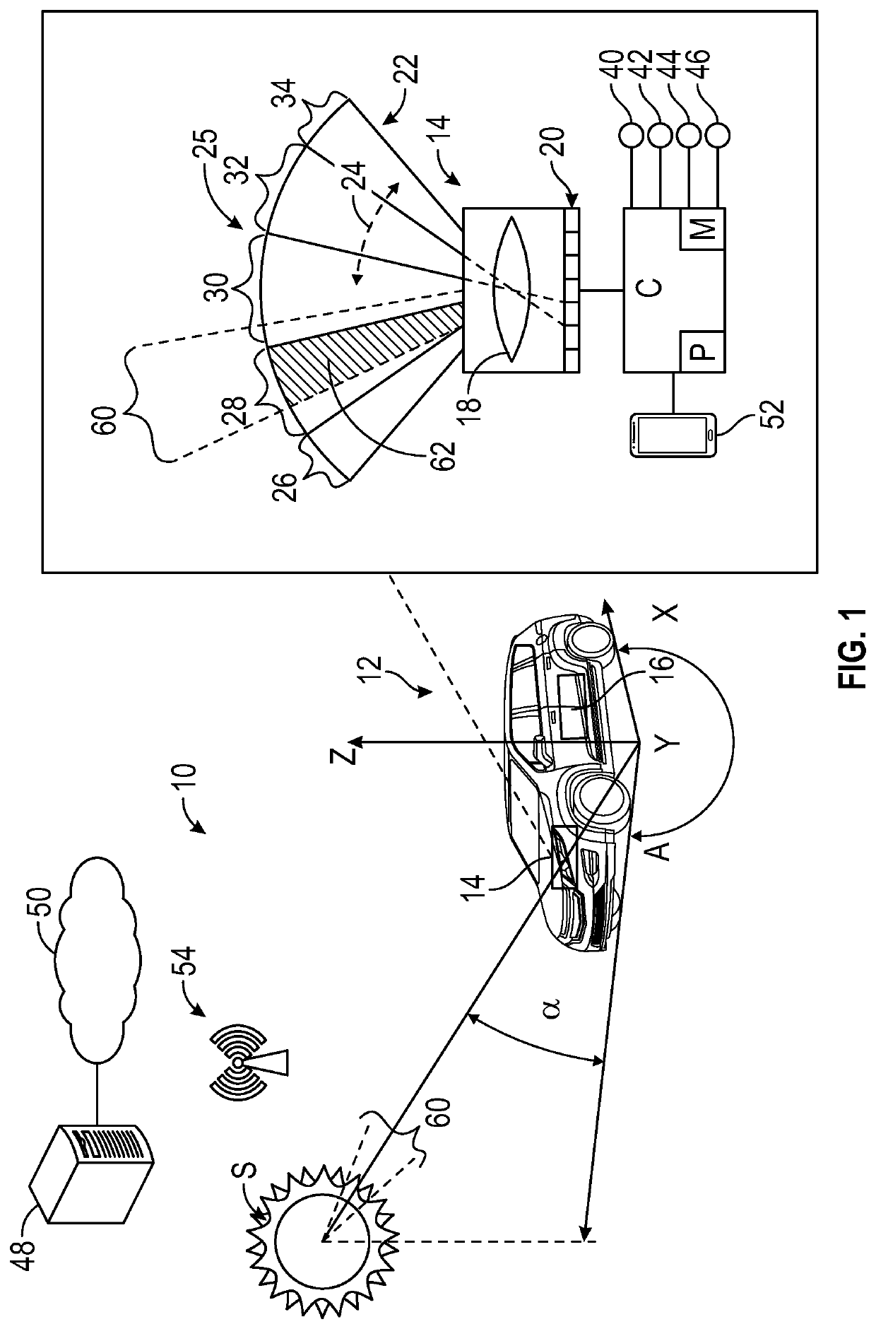
[0011]Referring to the drawings, wherein like reference numbers refer to like components, FIG. 1 schematically illustrates a system 10 for controlling operation of a device 12 in real-time. The device 12 includes at least one optical sensor 14 configured to provide an image about the device 12. The location of the optical sensor 14 on the device 12 may be varied based on the application at hand. The device 12 may include additional optical sensors, such as a second optical sensor 16 shown in FIG. 1. The device 12 may be a mobile platform such as, but not limited to, a passenger car, sport utility car, light truck, heavy duty truck, ATV, minivan, bus, transit vehicle, bicycle, robot, farm implement (e.g. tractor), sports-related equipment (e.g. golf cart), boat, airplane and train. The device 12 may take many different forms and include multiple and / or alternate components and facilities.

[0012]The optical sensor 14 is shown in greater detail in the inset of FIG. 1. The optical sensor...


PUM


Abstract

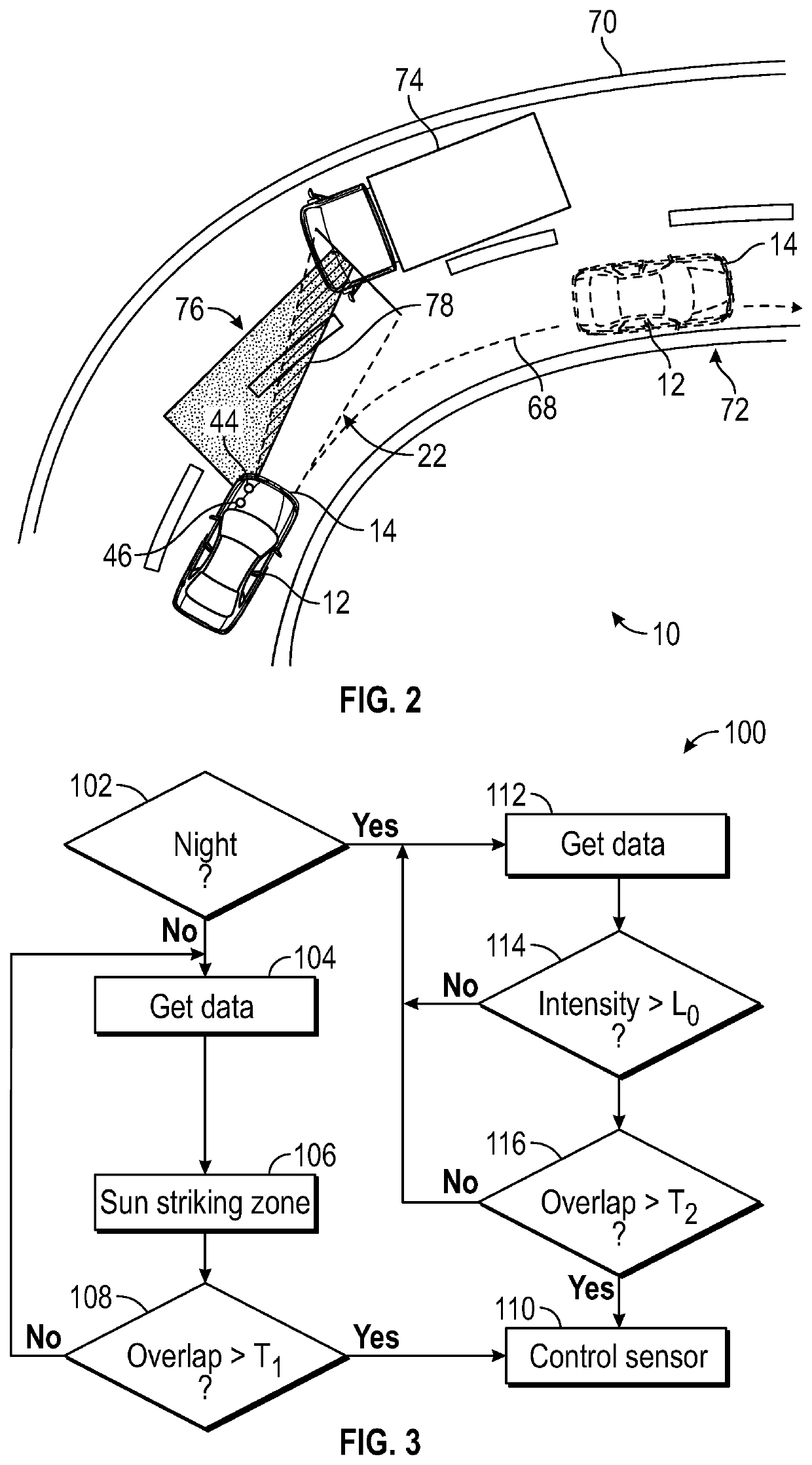
System and method of controlling operation of an optical sensor in a device. The optical sensor is configured to employ a scan pattern to scan respective portions of a full field of view. A navigation sensor is configured to obtain location coordinates of the device. An inertial sensor is configured to obtain an acceleration data of the device in a plurality of directions. A controller is configured to determine a position of the device at the present time based in part on the location coordinates and the acceleration data. The controller is configured to determine a sun striking zone based in part on a relative position of the sun and the device. When a sun overlap region between the respective portions of the full field of view and sun striking zone exceeds a first overlap threshold, operation of the optical sensor is modified.

Description

INTRODUCTION[0001]The present disclosure relates to a system and method of controlling operation of a device having an optical sensor. Optical sensor systems are often employed in automobiles and other transportation devices to provide a visual image of areas surrounding the devices. The devices may encounter bright light sources which may cause the optical sensors to be saturated and momentarily unable to perform measurements in the field of view of the optical sensor.SUMMARY[0002]Disclosed herein is a system and method of controlling operation of a device having at least one optical sensor. The optical sensor is operatively connected to the device and configured to employ a scan pattern to scan respective portions of a full field of view. The system includes a navigation sensor, such as a global positioning satellite (GPS) sensor, configured to obtain location coordinates of the device. An inertial sensor is configured to obtain an acceleration data of the device in a plurality of...

Claims


Application Information

Patent Timeline
IPC IPC(8): G01S17/46G01S17/89G01S7/48G01S17/02G01S13/86
CPCG01S7/4808G01S13/865G01S17/89G01S17/46G01S17/86G01C21/28G01S3/7862G01S2013/93271G01S17/931G01S17/42G01S7/497
Inventor PHILIPP, TZVIBILIK, IGALVILLEVAL, SHAHAR
Owner GM GLOBAL TECH OPERATIONS LLC
Learn More