Transceiver module

a transceiver module and module technology, applied in the direction of optical elements, coupling device connections, instruments, etc., can solve the problems of reducing the reliability of the transceiver module and the electronic device, the transceiver module may be unintentionally detached from the socket, and the transceiver module may not be properly locked, etc., to achieve convenient repair or adjustment, high reliability, and easy locking or unlocking

Inactive Publication Date: 2020-10-22
DELTA ELECTRONICS INC
View PDF0 Cites 2 Cited by
  • Summary
  • Abstract
  • Description
  • Claims
  • Application Information

AI Technical Summary

Benefits of technology

[0028]As mentioned above, the transceiver module of this disclosure comprises a springy sheet, so the transceiver module has higher reliability and can be easily locked or u...

Problems solved by technology

However, in the case of using the spring for locking or unlocking the transceiver module and the socket, the transceiver module may be unintentionally detached from the socket due to vibration, or the transceiver mo...

Method used


Image

  • Transceiver module
  • Transceiver module
  • Transceiver module

Examples


first embodiment

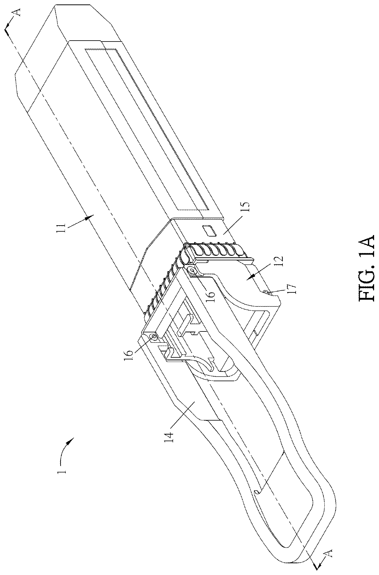
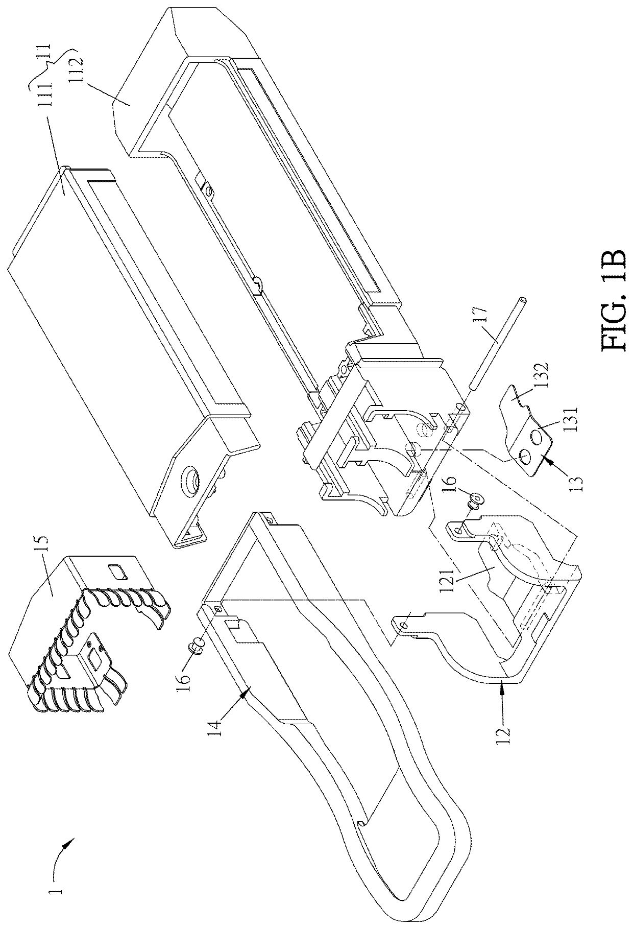
[0043]FIG. 1A is a schematic diagram showing a transceiver module 1 according to this disclosure, and FIG. 1B is an exploded view of the transceiver module 1 of FIG. 1A. Referring to FIGS. 1A and 1B, the transceiver module 1 comprises a housing 11, a latch 12, a springy sheet 13, and a pull tab 14. The latch 12 has a wedging portion 121 and is movably connected to the housing 11. The springy sheet 13 is disposed between the housing 11 and the latch 12. The pull tab 14 is connected to the latch 12. As shown in the drawings, the pull tab 14 is pivotally connected to the latch 12 through a first pivoting member 16, and the latch 12 is movably connected to the housing 11 through a second pivoting member 17.

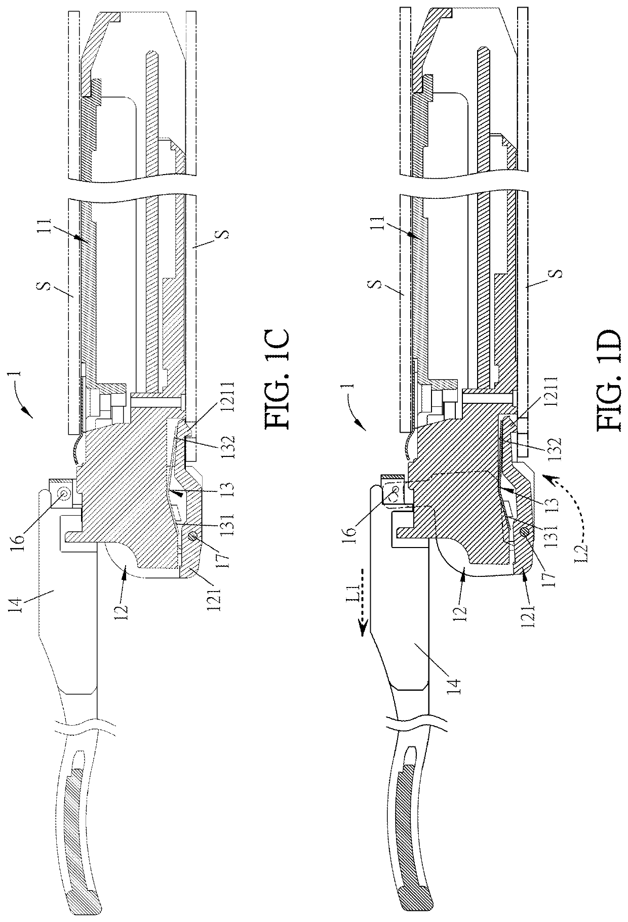
[0044]FIG. 1C is a sectional view of the transceiver module 1 along the line A-A of FIG. 1A, wherein the transceiver module 1 and the socket S are in a lock status. FIG. 1D is a sectional view of the transceiver module 1, wherein the transceiver module 1 and the socket S are in an unl...

second embodiment

[0049]FIG. 2C is a sectional view of the transceiver module 2 along the line B-B of FIG. 2A, wherein the transceiver module 2 and the socket S are in a lock status. FIG. 2D is a sectional view of the transceiver module 2, wherein the transceiver module 2 and the socket S are in an unlock status. In the second embodiment, the pull tab 24 moves from a first pull tab position (see FIG. 2C) to a second pull tab position (see FIG. 2D) by rotating (shown as the arrow L3 of FIG. 2D). When the pull tab 24 moves from the first pull tab position (see FIG. 2C) to the second pull tab position (see FIG. 2D), the pull tab 24 applies a force to move the latch 22 with relative to the housing 21 (shown as the arrow L4 of FIG. 2D) and to carry the wedging portion 221 to move from a first wedging position (see FIG. 2C) to a second wedging position (see FIG. 2D). Accordingly, the wedging bump 2211 can be sunk inwardly, so the transceiver module 2 can be detached from the socket S. In more detailed, whe...


PUM


Abstract

A transceiver module includes a housing, a latch, a springy sheet, and a pull tab. The latch has a wedging portion and is movably connected to the housing. The springy sheet is disposed between the housing and the latch. The pull tab is connected to the latch. When the pull tab moves from a first pull tab position to a second pull tab position, the pull tab applies a force to move the latch with relative to the housing and to carry the wedging portion to move from a first wedging position to a second wedging position, thereby deforming the springy sheet. When the force applied by the pull tab is removed, the springy sheet pushes the wedging portion to move from the second wedging position to the first wedging position.

Description

CROSS REFERENCE TO RELATED APPLICATIONS[0001]This Non-provisional application claims priority under 35 U.S.C. § 119(a) on Patent Application No(s). 201910316495.1 filed in People's Republic of China on Apr. 19, 2019, the entire contents of which are hereby incorporated by reference.BACKGROUND OF THE INVENTIONField of Invention[0002]The present disclosure relates to a transceiver module and, in particular, to a transceiver module with a springy sheet.Related Art[0003]In the optical communication products, such as network apparatuses (e.g. hub), at least one transceiver module is configured for transforming the optical signals to the electrical signals. The fiber can connect to the network apparatus through the above-mentioned transceiver module. In order to increase the flexibility of system design and the convenience of repairing, the transceiver module is plugged into a corresponding socket of the communication device. In general, the socket is disposed on the circuit board. In ord...

Claims


Application Information

Patent Timeline
IPC IPC(8): H01R13/627G02B6/42
CPCG02B6/4278H01R13/6275G02B6/4261G02B6/4256G02B6/4285H01R13/6335
Inventor LU, CHEN-MAOCHUANG, WEN-CHINGSU, LI-HUA
Owner DELTA ELECTRONICS INC
Why Eureka
Try Eureka