Supercharge Your Innovation With Domain-Expert AI Agents!

Eye tracking for head-worn display

Inactive Publication Date: 2020-10-29
BAE SYSTEMS PLC
View PDF0 Cites 2 Cited by
  • Summary
  • Abstract
  • Description
  • Claims
  • Application Information

AI Technical Summary

Benefits of technology

The invention is about a display assembly for a head-mounted device that includes a partially reflective and transparent surface located in the user's field of view. The display projector projects light onto the reflective surface for reflection towards the user's eyes, and there is also a sensor to track the user's eye movements. This technology can be used in applications such as eye-tracking and augmented reality. The display assembly can also include additional features such as non-visible illumination and synchronized sensing of the eye tracking and display output.

Problems solved by technology

The optimum position for the camera and light source is in front of the face, and hence obscures the user's vision.
Also, the IR illumination is not contained and hence in the case of a pilot may leak out of the cockpit which is disadvantageous from a detection standpoint.

Method used


Image

  • Eye tracking for head-worn display
  • Eye tracking for head-worn display
  • Eye tracking for head-worn display

Examples


Embodiment Construction

[0020]Further details, aspects and embodiments of the invention will now be described, by way of example only, with reference to the drawings. Elements in the figures are illustrated for simplicity and clarity and have not necessarily been drawn to scale. Like reference numerals have been included in the respective drawings to ease understanding.

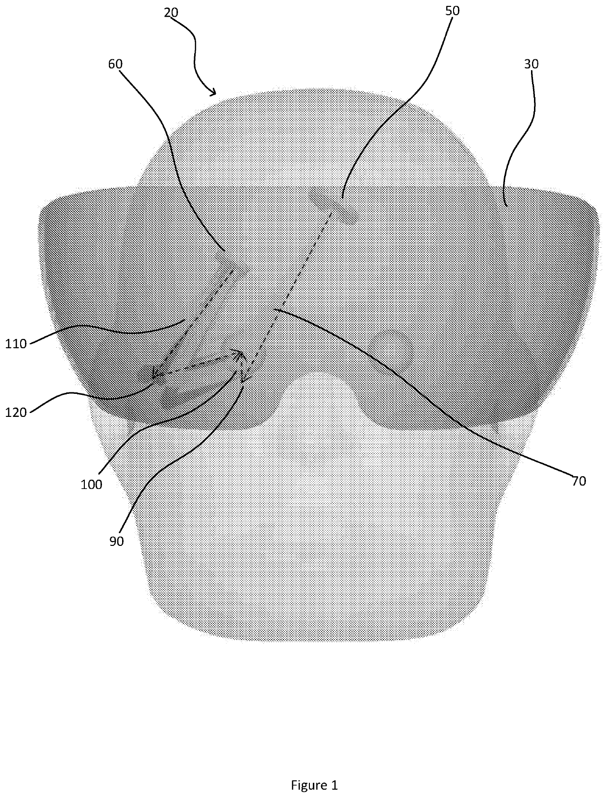
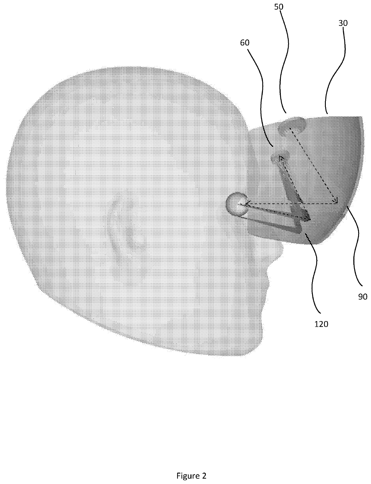
[0021]By way of introduction, some issues with current eye tracking technologies will be set out. They illuminate the eye with infra-red light (IR) and use a camera to track the position of the user's pupil by determining the contrast difference between the pupil (which absorbs the IR and therefore appears dark) and the sclera (which reflects the IR and therefore appears white). If such a system were included in a visor projected display, illuminating and imaging the eye correctly becomes difficult since the ideal position for the illumination and camera sits in line with the projected display optics path. To address this problem, it has now...


PUM


Abstract

A display assembly (105) for mounting on a head-worn device such as a helmet, and having a partially reflective surface located in a field of view of a user, a display projector (40, 50, 200) for projecting light towards the user via the partially reflective surface, a sensor (60, 210) for use in tracking an eye of the user, and a partially reflective imaging surface (120, 220, 225) located in the field of view. The sensor is aligned to receive light forming an image of an eye reflected by the partially reflective imaging surface, the image being for use in the eye-tracking. By using a reflected image, the camera location can be arranged to improve the potentially conflicting needs of keeping the field of view clear, and of having an image from directly in front of the eye, and of limiting the weight and size and imbalance of the helmet. The visor may be used as the partially reflective surface. IR Illumination may be provided by the display projector.

Description

FIELD OF THE INVENTION[0001]This disclosure relates to tracking a user's eyes, and in particular such tracking performed on a user wearing a head-worn device for display such as a Head Up Display (HUD).BACKGROUND ART[0002]Eye tracking enables a system to monitor the position of a user's eyes in their head and hence calculate the direction of vision. Such systems are particularly useful in conjunction with Head Up Displays which use a transparent component to project images into the user's field of view. For example, data may be overlaid on a view for a pilot, or a night-vision system may be used to project an augmented view over the dark natural view.[0003]Head-worn devices having displays are systems which are mounted to the helmet (or other headpiece) of a user such that the transparent components are positioned in front of a user's eyes even as their head is moved. Such displays may use a specific set of optics positioned in front of the user's eyes, or may use a visor to project...

Claims


Application Information

Patent Timeline
IPC IPC(8): G02B27/00G02B27/01G02B27/14G06F3/01
CPCG02B2027/0138G06F3/013G02B27/144G02B27/0172G02B27/0093G02B27/0101G02B2027/014G02B2027/0187
Inventor MILLS, RORY THOMAS ALEXANDERSIMMONDS, MICHAEL DAVID
Owner BAE SYSTEMS PLC
Features
  • R&D
  • Intellectual Property
  • Life Sciences
  • Materials
  • Tech Scout
  • Unparalleled Data Quality
  • Higher Quality Content
  • 60% Fewer Hallucinations
Learn More