Generic depth indicator for surgical navigational tools

a technology of depth indicators and surgical navigation, applied in the field of surgical navigation devices, can solve problems such as inability to adjust, inability to adjust, and inability to adjust, and achieve the effect of clear tracking line of sigh

Pending Publication Date: 2020-11-05
MAZOR ROBOTICS
View PDF6 Cites 3 Cited by
  • Summary
  • Abstract
  • Description
  • Claims
  • Application Information

AI Technical Summary

Benefits of technology

[0009]The device comprises three basic components—a pair of spaced apart end caps, conveniently in the form of thin plate-like elements, which are kept separated by a compressed spring. The surgical tool passes through axial openings in both end caps, and is firmly attached to a first one of the end caps, but free to slide through the opening in the second. A guide tube is advantageously attached to the second end cap, such that the surgical tool passing through the opening in the second end cap can be accurately guided to its operating position on a body part. This second end cap and guide tube are attached to a location having a known position relative to the body part. A tracking marker is attached to the first end cap such that its longitudinal position relative to the second cap fixed to the location having a known position relative to the body part, can be tracked using a remote navigation or tracking camera, as part of a navigation or tracking system. Since the surgical tool is firmly attached to the first end cap, the tool position relative to the body part is also tracked by the tracking system, and hence also the operating end of the tool, whose depth of entry into the body part, the device it is intended to monitor. The tracking marker is mounted on a rotating arm, allowing the marker to rotate freely in 360 degrees around the device axis, such that a clear tracking line of sight can be obtained regardless of obstructions generated during the surgical procedure.

Problems solved by technology

Errors in depth can easily cause irreversible disability or fatality, for example, in spinal procedures, by accidental insertion of sharp tools and implants beyond the vertebrae into the spinal cord or aorta.
Both of these devices are handheld tools with specific and limited uses.
Several problems exist with current navigational devices, leaving the field with a need for a solution that rectifies these deficiencies.
One problem is the need for calibration.
Not only is this technical verification process time-consuming—it is also prone to human error.
A second difficulty is that in many prior art systems, a positional marker is attached to the tool and viewed by an associated navigation system.
If the marker moves out of view of the camera because the tool was rotated by the operator or positioned behind another object, the tool will lose connection with the remote navigation system and thus cease to preserve its relative position, thereby losing its ability to indicate depth.
Finally, with current surgical navigation systems, the process of tool calibration is generally limited to designated tools compatible with a given navigation system.

Method used


Image

  • Generic depth indicator for surgical navigational tools
  • Generic depth indicator for surgical navigational tools

Examples


Embodiment Construction

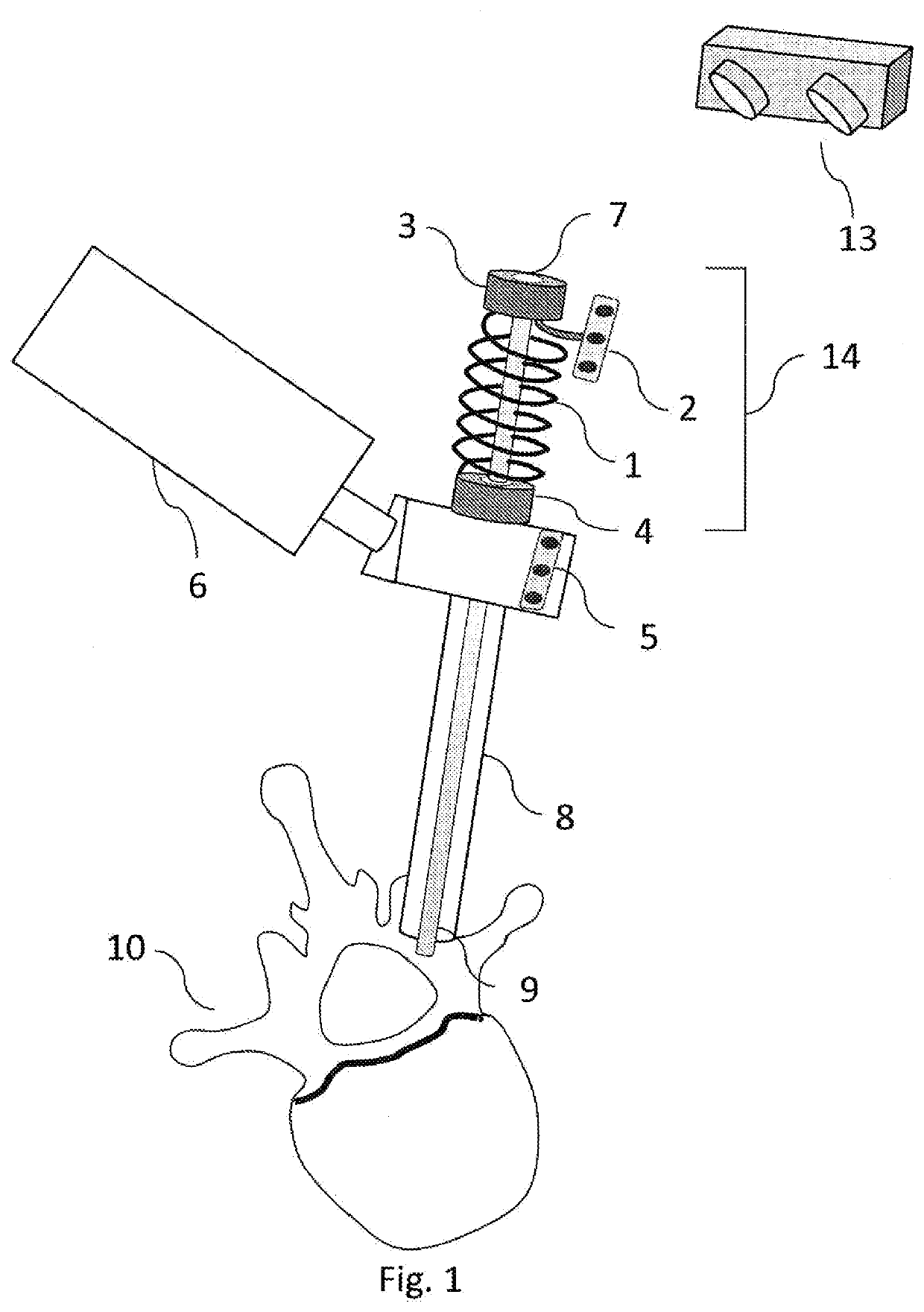
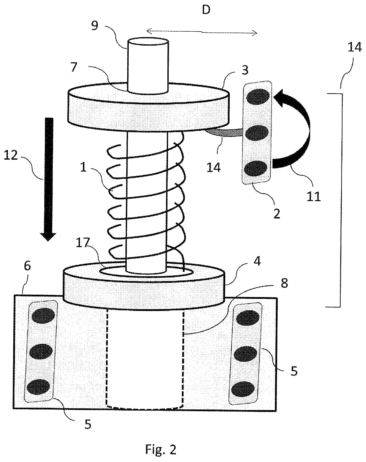
[0026]Reference is now made to FIG. 1, which illustrates schematically one example of the generic depth indicator of the present disclosure. A spring 1 is contained between end caps 3, 4 by each of its ends. The unloaded length of the spring must be greater than the maximum distance between the end caps 3, 4, in order to always maintain the spring in a minimally compressed state end, such that the end caps 3, 4, are always at a clearly defined distance apart, for any normal mutual position of the end caps. The proximal end cap 3, contains an opening 7 into which a surgical tool 9 can be inserted and attached to the end cap 3, such that the cap moves with motion of the tool, or vice versa. The term proximal is used throughout this disclosure to relate to that end of an element closer to the operator, while the term distal relates to the end closer to the subject. To the proximal cap is attached a navigation marker 2, which can optionally rotate around the axis of the device through 3...


PUM

PropertyMeasurementUnit
depthaaaaaaaaaa
compressibleaaaaaaaaaa
lengthaaaaaaaaaa

Abstract

A depth-indicating device for determining the depth of insertion of a surgical tool comprising a pair of spaced apart end caps, separated by a compressed spring, with the surgical tool passing through axial openings in both end caps, and firmly attached to one of the end caps, but free to slide through the opening in the other. A guide tube is attached to the second endcap, such that the surgical tool can be guided to its operating position on a body part. The second end cap and guide tube are attached to a location having a known position relative to the body part. A tracking marker is attached to the first end cap such that its longitudinal position can be tracked using a remote racking camera. Since the surgical tool is attached to the first end cap, the tool position is also tracked by the tracking system.

Description

FIELD OF THE INVENTION[0001]The present invention relates to the field of devices used in surgical navigation, especially minimally invasive procedures, for use in determining the insertion depth of a surgical tool.BACKGROUND OF THE INVENTION[0002]Depth indication is an important part of surgical navigation capability, allowing for the user to observe and be alerted to the current real-time depth of a surgical trajectory in comparison to patient anatomical landmarks. This capability is necessary especially in procedures in which the surgeon is operating under video-guided or other forms of indirect vision, to prevent as much as possible, depth-related errors. In minimally invasive procedures, the ability to accurately determine the depth of a surgical tool is important because of the practical inability to properly assess distance in a three dimensional scenario, without a proper line of sight. Errors in depth can easily cause irreversible disability or fatality, for example, in spi...

Claims


Application Information

Patent Timeline
Patent Type & Authority Applications(United States)
IPC IPC(8): A61B34/20A61B34/30A61B90/00A61B90/11B23B49/00
CPCB23B49/005A61B17/1615A61B2034/2055A61B34/20A61B2090/062A61B2090/3937A61B90/06A61B90/11B23B2260/0482A61B34/30B23B47/28B23B2270/32
Inventor JUNIO, DANYPOELSTRA, KORNELIS
Owner MAZOR ROBOTICS
Why Eureka
Try Eureka