Dental Irrigation Device

a dental tissue and water supply technology, applied in the direction of dissolving systems, transportation and packaging, dissolving, etc., can solve the problems of wasting water and requiring water to run for a long time, and achieve the effect of promoting dental health

Active Publication Date: 2020-11-05
GOODSON MARK E
View PDF0 Cites 0 Cited by
  • Summary
  • Abstract
  • Description
  • Claims
  • Application Information

AI Technical Summary

Benefits of technology

[0007]The present invention utilizes heating and mixing componentry to raise the temperature of the water and to mix a solute within the solution before the solution is introduced into the oral cavity by way of pressurized water jet. The invention present invention comprises a basin, heating / mixing componentry, base, a pump, and a handheld dispenser. Normal tap water is placed in a basin which is delivered via pump to a dispenser. In one embodiment, an inductor coil is utilized within the basin to heat and mix the solute with the solution. In a second embodiment, a ferrous slug rotates within the basin mixing the solute with the solution. As this mixed solution is delivered to the dispenser via a pump, the solution passes through a heating chamber using a ferrous inductor coil system that heats the solution. The pressurized solution is then delivered to the dispenser which allows for a jet stream of solution to be aimed by the user at the affected dental tissue. The pressurized solution stream can dislodge particulate accumulations, thereby promoting dental health. The pump has a modulating system that can alter the solution stream to have either continuous flow or pulsed characteristics. The open top basin allows the addition of salts or medicine to the solution for treatment of medical conditions.

Problems solved by technology

However if the sink's hot water faucet is located away from the hot water heater, this system requires the water to run for a lengthy period of time wasting water.

Method used


Image

  • Dental Irrigation Device
  • Dental Irrigation Device
  • Dental Irrigation Device

Examples


first embodiment

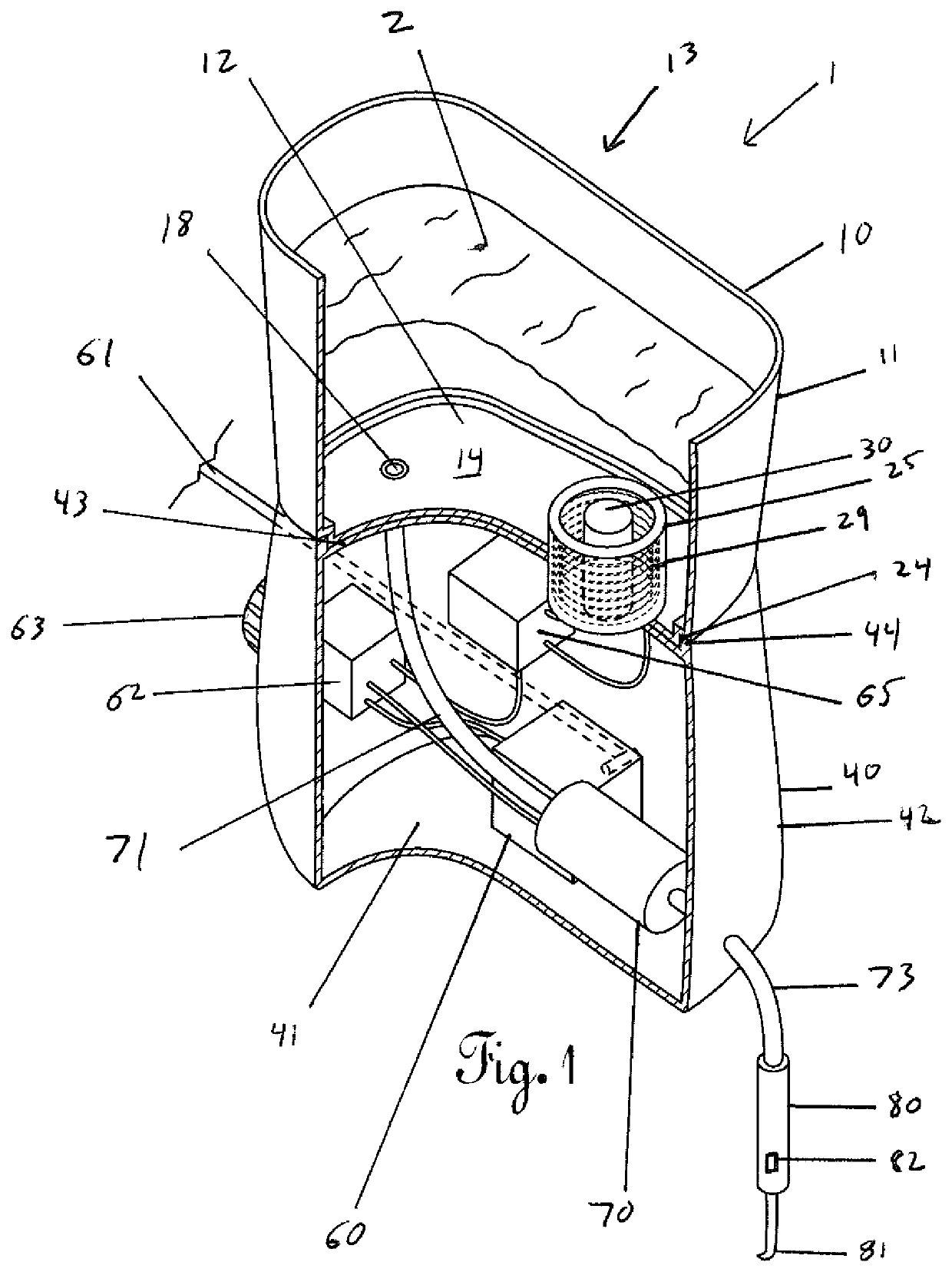
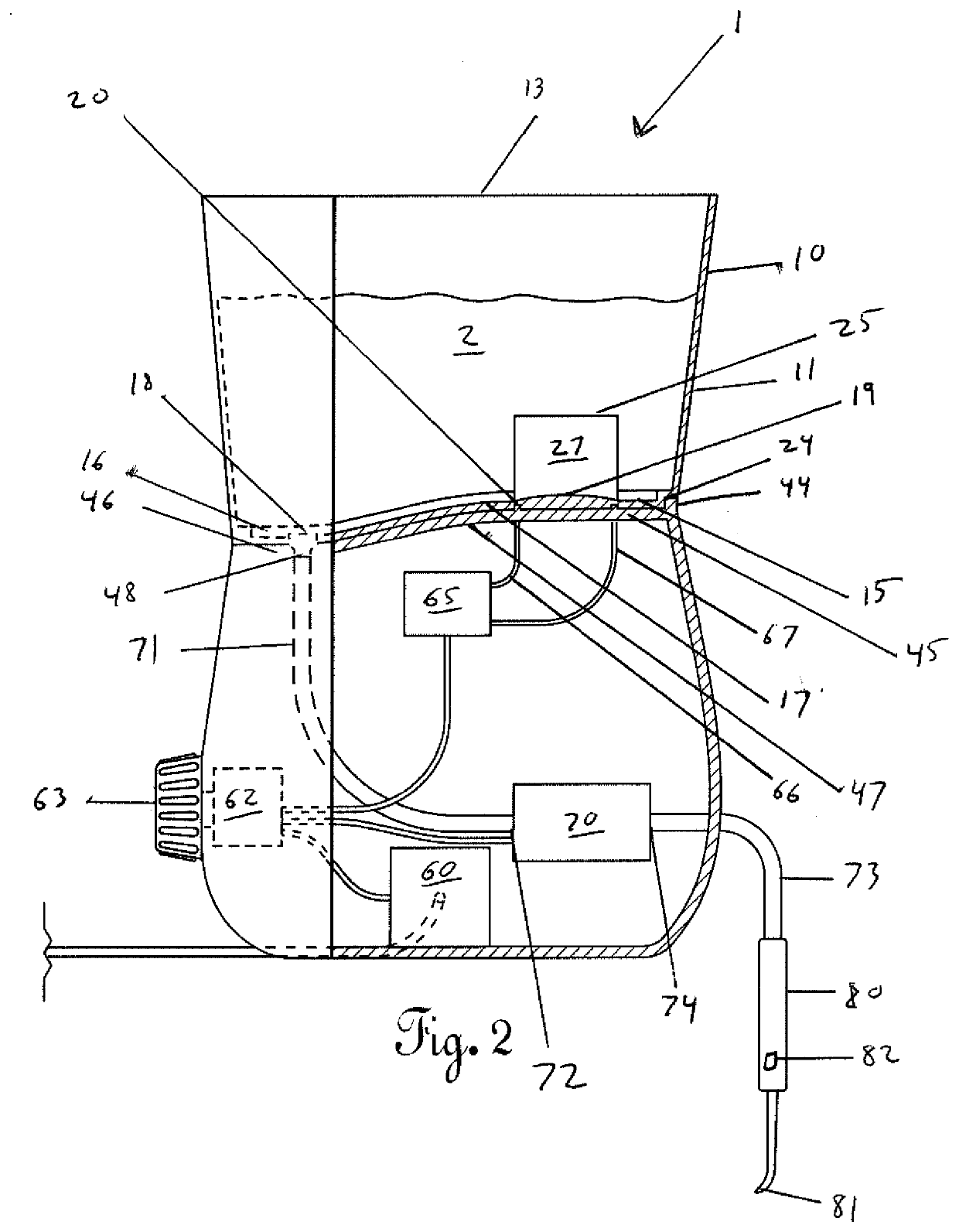
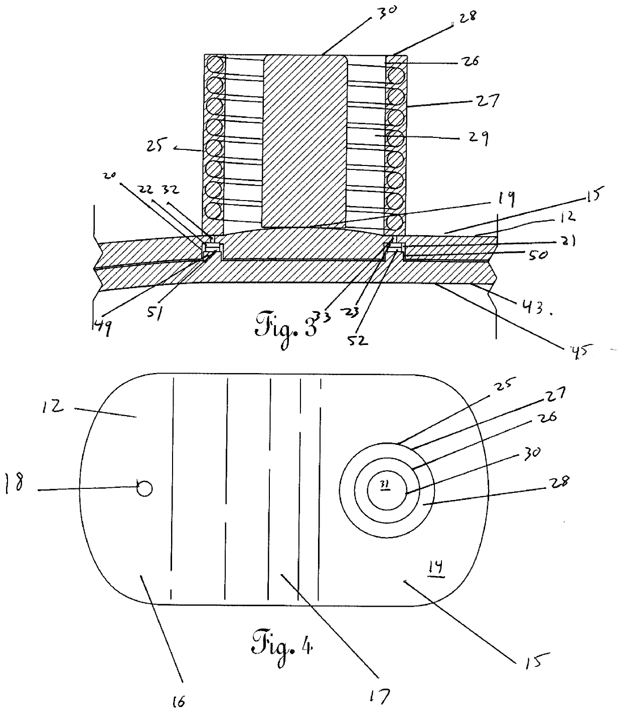
[0020]FIGS. 1-5 disclose a dental irrigation device 1 comprising a basin 10, a base 40, and a dispenser 80. The basin 10 comprises a sidewall 11, a bottom wall 12, and an open top 13. Alternatively a removable lid may be placed on top of the basin 10. The top surface 14 of the bottom wall 12 is continuous having a raised portion 15 and a lowered portion 16 connected by a slope 17. The lower portion 16 may further slope to a port 18. The raised portion 15 further contains a convex portion 19. A first recess 20 and a second recess 21 are positioned within the bottom surface of the raised portion 15 of the bottom wall 12. The first recess 20 and second recess 21 are positioned adjacent to the convex portion 19 on the top surface 14 of the bottom wall 12. A first metal connectivity tab 22, and second metal connectivity tab 23 are positioned at the top of the first recess 20 and second recess 21 respectively. A continuous notch 24 is formed at the juncture of the sidewall 11 and bottom w...

second embodiment

[0028]FIGS. 6-11 disclose a dental irrigation device 100 comprising a basin 110, a base 140, and a dispenser 180. The basin 110 comprises a sidewall 111, a bottom wall 112, and an open top 113. Alternatively a removable lid may be placed on top of the basin 110. The top surface 114 of the bottom wall 112 is continuous having a raised portion 115 and a lowered portion 116 connected by a slope 117. The lower portion 116 may further slope to a port 118. A continuous notch 124 is formed at the juncture of the sidewall 111 and bottom wall 112.

[0029]A circular cage 125, having side posts 126 and top posts 127, is positioned on the raised portion 115 of the bottom wall 112 of the basin 110. A ferrous slug 130 having a polymer surface coating 131 is positioned inside the circular cage 125. The length of the ferrous slug 130 is longer than length of the side posts 126 but shorter than the diameter of the circular cage 125.

[0030]The base 140 comprises a bottom wall 141, sidewall 142, and top ...


PUM

PropertyMeasurementUnit
tap temperatureaaaaaaaaaa
temperatureaaaaaaaaaa
solubilityaaaaaaaaaa

Abstract

A dental irrigation device for heating a solution and mixing solutes within the solution. The present invention utilizes an oscillator and inductive coil to heat and / or mix the solution. A pump then delivers the heated and mixed pressurized solution from a basin ultimately into a dispenser.

Description

CROSS REFERENCE TO RELATED APPLICATIONS[0001]This application claims the benefit of and priority to U.S. Provisional Application No. 62 / 833,736, filed Apr. 14, 2019, entitled “Dental Irrigation Device.” This application is incorporated by reference.STATEMENT REGARDING FEDERALLY SPONSORED RESEARCH OR DEVELOPMENT[0002]Not ApplicableBACKGROUND OF THE INVENTION1. Field of the Invention[0003]The present invention relates to a device for the aqueous irrigation of dental tissue.2. Description of the Related Art[0004]It is well known that dental tissue benefits from the addition of certain solutes when the teeth and gums are irrigated, with water being considered as the solvent. Such solutes include salt, mouthwashes, and hydrogen peroxide. The matter and sufficiency for which they dissolve and mix are based on two major factors, dispersion and temperature. The temperature factor is even more important in certain compounds such as salt because solubility increases as temperature rises.[0005...

Claims


Application Information

Patent Timeline
Patent Type & Authority Applications(United States)
IPC IPC(8): A61C17/02B05B9/00B05B9/04B01F1/00B01F15/06
CPCB01F2215/0027B05B9/0403B05B9/002B01F1/0038B01F15/065B01F2015/062A61C17/02B01F21/00B01F33/12B01F31/85B01F33/452B01F35/93B01F2035/99B01F21/30B01F35/92B01F2101/19
Inventor GOODSON, MARK E.
Owner GOODSON MARK E
Why Eureka
Try Eureka