An apparatus and method for fiducial marker alignment in electron tomography

an electron tomography and fiducial marker technology, applied in image data processing, instruments, computing, etc., can solve the problem that the recorded micrographs do not exactly align with the recorded parameters, and achieve the effect of improving the alignment of a large number of fiducial markers

Active Publication Date: 2020-11-05
KING ABDULLAH UNIV OF SCI & TECH
View PDF0 Cites 0 Cited by
  • Summary
  • Abstract
  • Description
  • Claims
  • Application Information

AI Technical Summary

Benefits of technology

[0004]In general, embodiments of the present invention provided herein include apparatuses, methods, devices, and computer program products for aligning fiducial markers, fiducial marker tracking, and electron tomography. In some embodiments, provided is an apparatus for fiducial marker alignment, the apparatus comprising a processor and a memory storing computer instructions that, when executed by the processor, cause the apparatus to align positions of the fiducial markers on two or more micrographs forming two or more point sets corresponding to the two or more micrographs; create a first set of matched fiducial markers and unmatched fiducial markers; transform unmatched fiducial markers into transformed point sets and match the unmatched fiducial markers resulting in a second set of matched fidicual markers. The matching of the second set of matched fiducial markers results in improved alignment of a large number of fiducial markers.
[0007]Provided herein are also methods for fiducial marker alignment, fiducial marker tracking, and electron tomography. In some embodiments, provided is a method for fiducial marker alignment, the method comprising aligning positions of the fiducial markers on two or more micrographs forming two or more point sets corresponding to the two or more micrographs; creating a first set of matched fiducial markers and unmatched fiducial markers; transforming unmatched fiducial markers into transformed point sets and match the unmatched fiducial markers resulting in a second set of matched fidicual markers. The matching of the second set of matched fiducial markers may result in improved alignment of a large number of fiducial markers.

Problems solved by technology

However, due to mechanical instability and specimen transformation, the recorded micrographs do not exactly align with the recorded parameters.
Applicant has identified a number of deficiencies and problems associated with conventional tilt series alignment.

Method used


Image

  • An apparatus and method for fiducial marker alignment in electron tomography
  • An apparatus and method for fiducial marker alignment in electron tomography
  • An apparatus and method for fiducial marker alignment in electron tomography

Examples


example operations

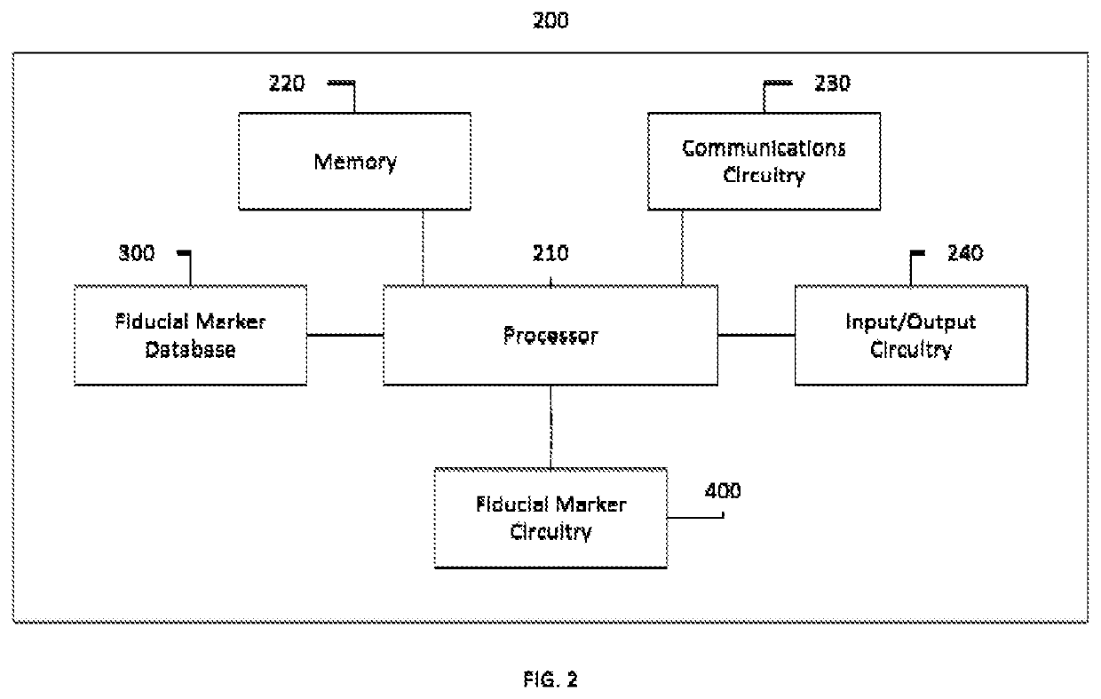
[0074]Marker-based alignment may include three stages: (i) fiducial marker detection, (ii) fiducial marker tracking and (iii) parameter optimization. In some embodiments, the apparatus 200 may include fiducial marker detection and parameter optimization. In some embodiments, apparatus 200 may be an electron tomography apparatus.

[0075]Provided herein, the relationship between a 2D model-based tracking and the 3D projection model is demonstrated. An upper bound of the deviation may be provided, within which the fiducial markers may be tracked in an affine transformation constrained model. Also provided is a series of solutions to allow for fiducial marker tracking.

[0076]Affine Relationship of Two Micrographs

[0077]In some embodiments, the projection is modeled as an affine or orthogonal projection. A classic orthogonal model is described as follows (in this section, the bold font is used to indicate vectors or matrices; a 2D point is represented by a 2×1 vector):

(uv)=sRγPRβRα(XYZ)+t,(1...


PUM


Abstract

Provided is an apparatus and method for aligning fiducial markers. The apparatus may align positions of the fiducial markers on the two or more micrographs forming a two or more point sets corresponding to the two or more micrographs; create a first set of matched fiducial markers and unmatched fiducial markers; transform unmatched fiducial markers into transformed point sets and match the unmatched fiducial markers resulting in a second set of matched fiducial markers. The matching of the second set of matched fiducial markers results in improved alignment of a large number of fiducial markers. The aligned positions of fiducial markers may be constrained by an upper bound of transformation deviation of aligning positions of fiducial markers on two or more micrographs.

Description

CROSS REFERENCE TO RELATED APPLICATIONS[0001]This application claims the benefit of U.S. Provisional Application No. 62 / 577,954 filed Oct. 27, 2017 and U.S. Provisional Application No. 62 / 690,013 filed Jun. 26, 2018, which are hereby incorporated by reference in their entirety.BACKGROUND[0002]Nowadays, three-dimensional (3D) structural analysis based on electron microscopy plays an important role in the field of structural biology. Among the various applications, electron tomography (ET) acts as a bridge between high-resolution structural analysis and cellular imaging. In ET, the 3D ultrastructure is reconstructed from a series of micrographs (tilt series) taken in different orientations. In some cases, the projection parameters can be recorded from the goniometer and used for further reconstruction. However, due to mechanical instability and specimen transformation, the recorded micrographs do not exactly align with the recorded parameters. To obtain high-quality 3D density from th...

Claims


Application Information

Patent Timeline
Patent Type & Authority Applications(United States)
IPC IPC(8): G06T7/33G06T3/00G06T7/00
CPCG06T2207/30204G06T3/0075G06T7/33G06T2207/10072G06T2207/10061G06T7/0012
Inventor GAO, XINHAN, RENMIN
Owner KING ABDULLAH UNIV OF SCI & TECH
Why Eureka
Try Eureka