Machine operational state and material movement tracking

a technology of machine operation and movement tracking, which is applied in the direction of vibration measurement in solids, instruments, navigation instruments, etc., can solve the problems of not having a ready, direct and/or cost-effective access to the operational state of the vehicle by third-party devices, such as after-market devices, and devices that cannot be readily and/or cost-effectively connected to the control system of the vehicl

Active Publication Date: 2020-11-12
BITSTRATA SYST INC
View PDF0 Cites 22 Cited by
  • Summary
  • Abstract
  • Description
  • Claims
  • Application Information

AI Technical Summary

Problems solved by technology

Often, devices designed or adapted to determine the operational state of a vehicle or a machine, particularly third-party devices, such as after-market devices, may not have a ready, direct and / or cost-effective access to the operational state of the vehicle.
For example, the devices cannot be readily and / or cost effectively connected with the control systems of the vehicle or the machine to determine the state of those control systems and to determine the operational state therefrom.
It may be further difficult due to technical, mechanical and / or cost issues, to affix sensors to various mechanical portions of the vehicle or the machine to detect the state of operation.
For example, it may be expensive, inconvenient or impossible to connect an aftermarket device to the control systems or otherwise to affix sensors to the mechanical portions of the vehicle or the machine after manufacture thereof.
The difficulty in connecting an aftermarket device to the control systems of a machine may be due to the lack of an interface or to restrictions of the use thereof, design, impediments to running additional wiring, and the like.
Furthermore, it may be inconvenient, or unreliable, to require the operator of the machine to manually determine the state of operation or otherwise actuate a separate control mechanism for doing so.
The use of time-outs is not ideal as it relies on expected behavior and not on sensed inputs.
Consequently, it may result in degraded system performance.
Vertical vibration may result in a time-variation in the weight measured over a period of time.
Traversing different terrain with each wheel causes some non-vertical vibrational modes due to side-to-side rocking of the vehicle.
Filter techniques can be used to reject some anomalies; however, system performance issues may persist.
Additionally, when the vehicle is a tractor-trailer combination, where the tractor and trailer are loosely mechanically coupled, such as when using a hitch clevis and drawbar, the vibration of the tractor as experienced by the trailer, such as vibration caused by the engine, is small when stopped, even while preparing to unload or unloading.
In some cases, due to issues such as mechanical binding, the measured weight after loading or unloading may not reach the actual weight immediately after loading or unloading.
Once the unloading has completed, the discharge gate is closed, any remaining grain in the auger is discharged, and the auger is disabled.
This is because certain machine designs suffer a problem wherein the stresses experienced by the weighing sensors are not properly relieved after unloading, referred to as “mechanical binding,” in other words, the measured weights may not be accurate, until the machine has moved some distance forward.
Additionally, the illustrations are merely representational and may not be drawn to scale.

Method used


Image

  • Machine operational state and material movement tracking
  • Machine operational state and material movement tracking
  • Machine operational state and material movement tracking

Examples


Embodiment Construction

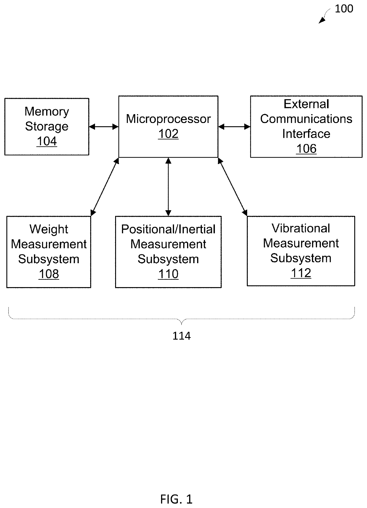
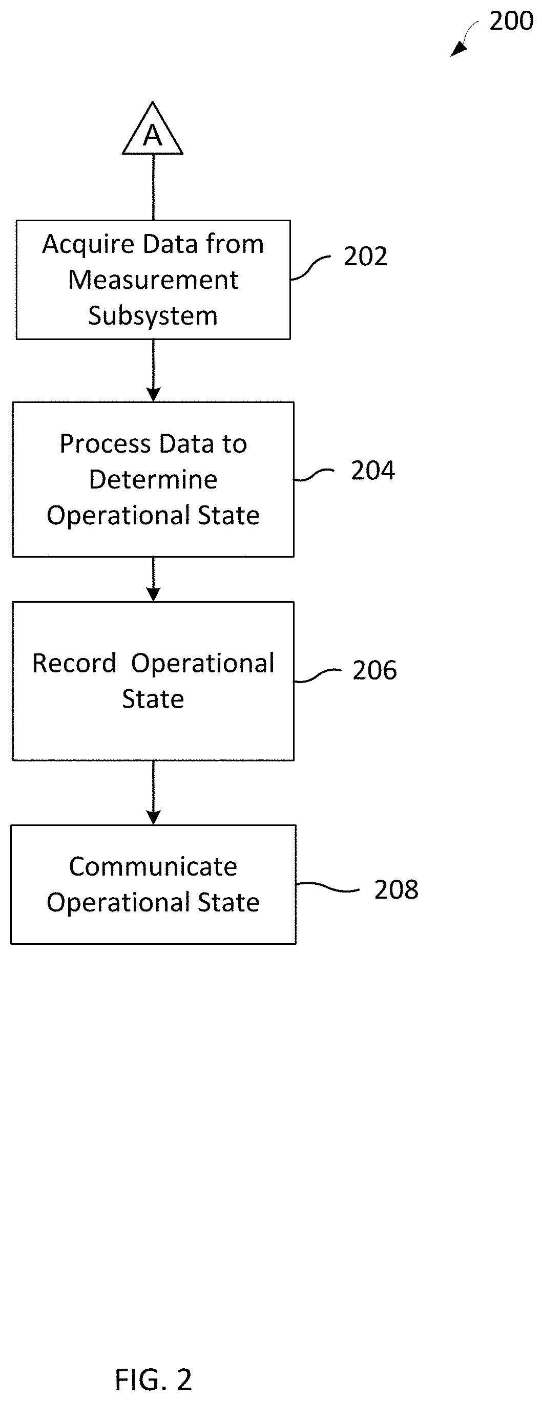
[0020]Aspects of the present disclosure overcome at least the problems and limitations of the prior art by providing an apparatus, a system, and a method that can indirectly detect and determine the operational state of the vehicle or the machine in a reliable and automatic fashion.

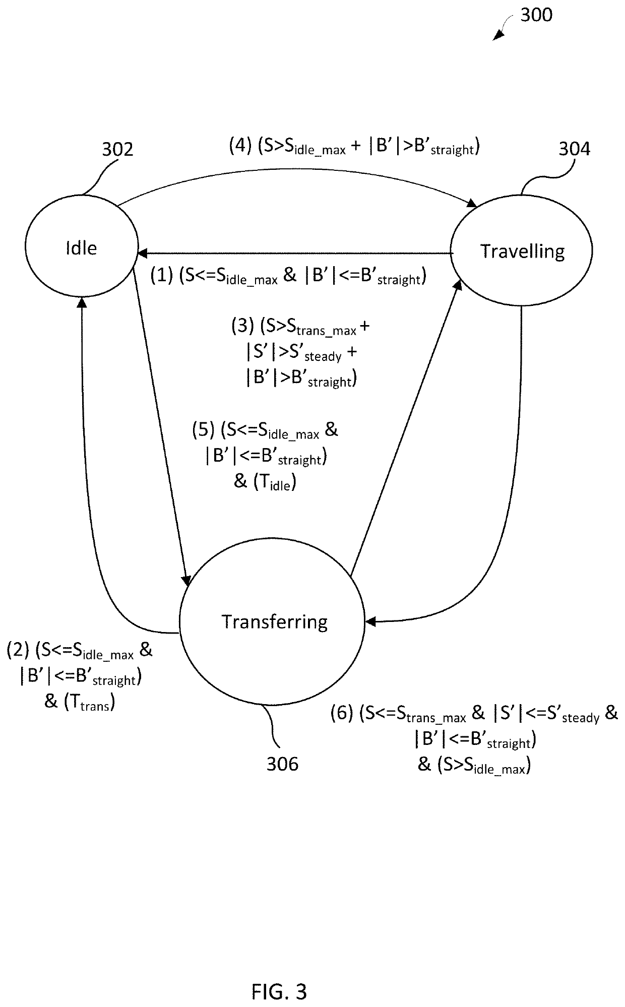
[0021]The apparatus, the system and the method may automatically collect data regarding the current, prior or future operational state of the vehicles or the machines for different purposes. The different purposes may include better business management, regulatory compliance, and the like. The machines may include farm vehicles. The operational state may include whether a vehicle or a machine is stationary, moving or travelling, preparing to transfer or transferring material, or loading or unloading. The current, prior or future operational state, or change / transition therebetween, may be used to calculate various metrics as will be described. It will be appreciated that these operational states may be re...


PUM


Abstract

An apparatus, a system and a method indirectly detect the operational state of a machine among a plurality of operational states and track the movement of a material through a plurality of machines.

Description

CROSS-REFERENCE TO RELATED APPLICATIONS[0001]This application claims priority to and the benefit under 37 C.F.R. 1.53(b) and 35 U.S.C. § 365 as a continuation application of PCT Application Serial No. PCT / CA2019 / 051509, filed on Oct. 24, 2019, and designating the United States, which claims the benefit of the filing date under 35 U.S.C. § 119(e) of U.S. Provisional Application Ser. No. 62 / 749,860 filed Oct. 24, 2018, the entirety of which are hereby incorporated by reference.FIELD OF THE DISCLOSURE[0002]The present disclosure relates to an apparatus, a system and a method for detecting the operational state of a machine. More particularly, the present disclosure relates to an apparatus, a system and a method to detect the operational state of a machine that has an onboard weighing and a payload transfer mechanism, and to track the movement of a material through a series of machines.BACKGROUND[0003]Various vehicles or machines, particularly those designed for the purpose of transport...

Claims


Application Information

Patent Timeline
Patent Type & Authority Applications(United States)
IPC IPC(8): A01D41/127G07C5/02G07C5/00G01G11/04G06Q10/06
CPCA01D41/127G01G11/04H04W4/029G06Q10/067G07C5/02G07C5/008G01M7/00G01H1/00G07C3/08G01C21/188
Inventor MEIER, IAN ROBERTLOCKERBIE, MICHAEL DAVID
Owner BITSTRATA SYST INC
Why Eureka
Try Eureka