Inflatable bladder system for bulk liquid transport

a technology of liquid transport and inflatable bladder, which is applied in the direction of fluid pressure control, instruments, transportation items, etc., can solve the problems of increased stress and fatigue, increased difficulty in safely braking, and increased difficulty in safe control of vehicles, so as to reduce stress and fatigue, and disperse energy within the tank

Pending Publication Date: 2020-11-12
HOULE SCOTT
View PDF25 Cites 1 Cited by
  • Summary
  • Abstract
  • Description
  • Claims
  • Application Information

AI Technical Summary

Benefits of technology

[0009]Traditional baffles typically only REDUCE surge and slosh in a FRONT TO BACK motion, but have NO benefits for SIDE TO SIDE surge, which is felt while on turns, or in an emergency swerve situation.
[0010]Unlike baffles that rely on blocking surge and transferring it through the tank to the truck, drop-in baffles (for example Surge Buster® drop-in baffles) dissipate energy within the tank. Nothing is securely attached to the walls of the tank. The resulting benefit to the liquid load hauler is a safer load, reduced stress and fatigue on the driver, plus a reduction in vehicle maintenance cost as well as longer tank life. However, one problem with the drop-in baffles is that it can be impractical for everyday use. Generally, someone has to climb onto the top of the tank and be handed hundreds of these drop in baffles, just to make a difference. But then what? Then you have to fish them out? Clean them? Store them somewhere until next time? This can be time consuming and impractical. Additionally, even with these drop in baffles, there is still some front to back surge, as well as side to side surge.

Problems solved by technology

Surge and slosh are big problems in the bulk liquid transport industry.
This continued movement can create a force that tends to make safely braking more difficult.
Moreover, even when stopped, the liquid may continue sloshing back and forth creating instability and making the vehicle more difficult to safely control.

Method used


Image

  • Inflatable bladder system for bulk liquid transport
  • Inflatable bladder system for bulk liquid transport
  • Inflatable bladder system for bulk liquid transport

Examples


Embodiment Construction

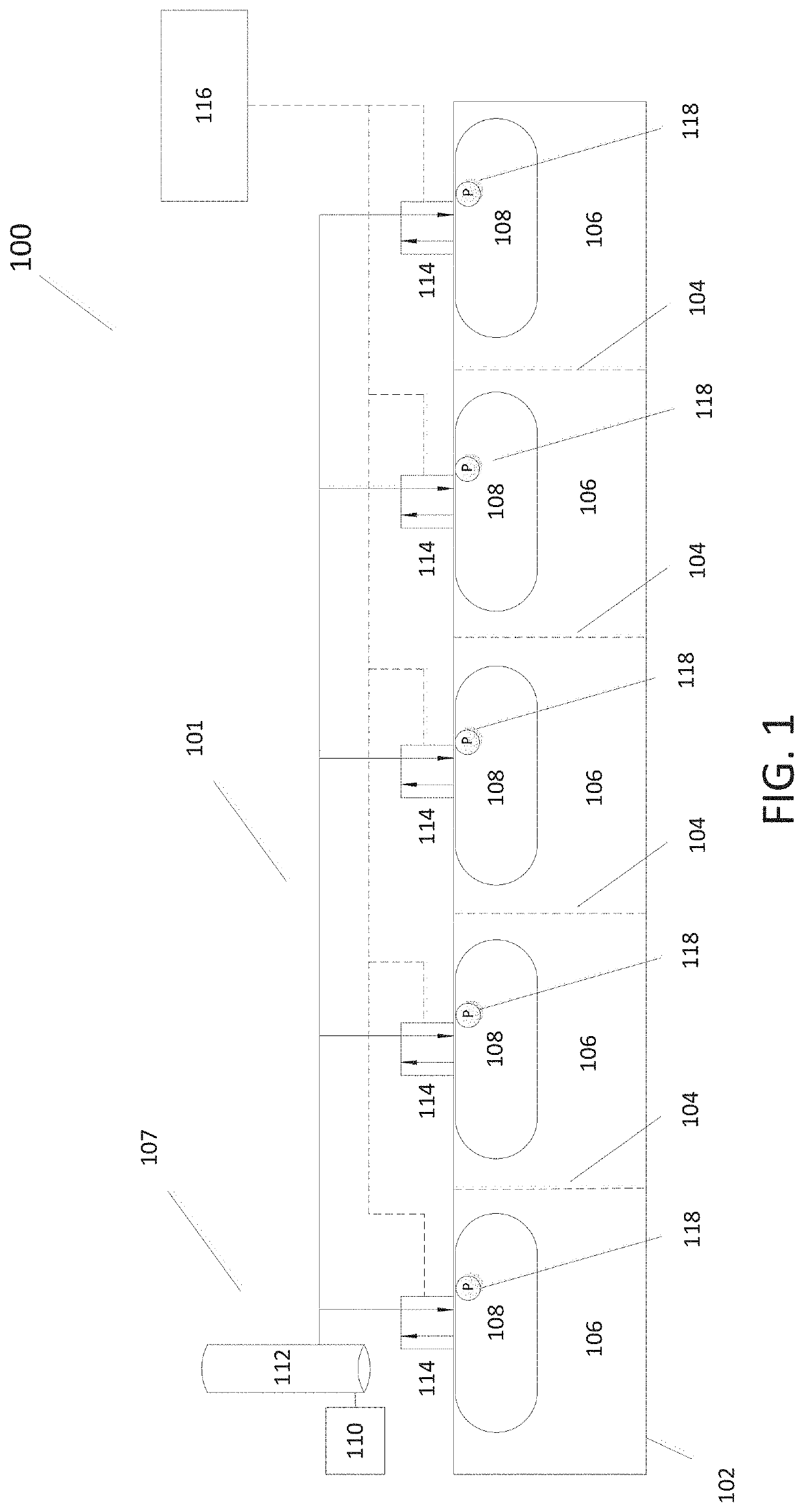
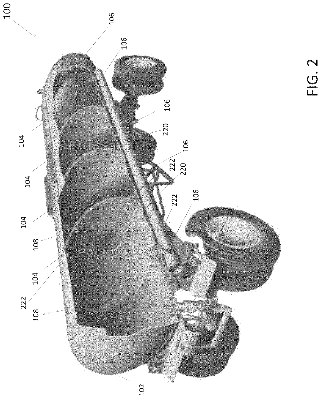
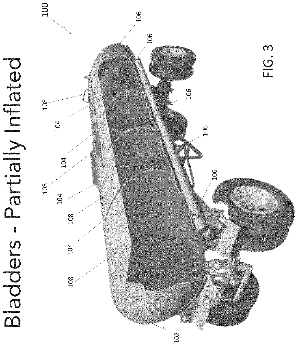
[0039]FIG. 1 is a partial schematic representation of a vehicle for transporting bulk liquids. More specifically, the vehicle represent in the illustrated implementation would have a tractor pulling a trailer (or some other means to roll along a road, for example). The trailer would be supporting bulk liquid storage tank 102.

[0040]Moreover, the illustrated vehicle 100 has an inflatable bladder system 101 for controlling undesirable movement (e.g., surge, slosh, etc.) of bulk liquid being transported within the tank 102. In a typical implementation, the inflatable bladder system 101 is able to control surge in virtually all directions, including longitudinally (i.e., defined by the vehicle's direction of motion) as well as laterally (i.e., side-to-side). Moreover, in a typical implementation, the inflatable bladder system 101 can control movement of the liquid anytime there is an amount of liquid in the tank 102 that has potential to create vehicle stability problems, regardless of w...


PUM


Abstract

A system (typically on a bulk liquid transport vehicle) includes a liquid storage tank, one or more liquid storage compartments inside the liquid storage tank, an inflatable bladder inside each of the liquid storage compartments, a compressed air system to provide compressed air to inflate each one of the inflatable bladders, and one or more valves. Each of the valves is configured to control air flow between the compressed air system and a corresponding one of the inflatable bladders and/or to control air flow between the corresponding inflatable bladder and atmosphere.

Description

CROSS-REFERENCE TO RELATED APPLICATION(S)[0001]This application claims the benefit of U.S. Provisional Patent Application Ser. No. 62 / 844,203, filed May 7, 2019, and entitled INFLATABLE BLADDER SYSTEM FOR BULK LIQUID TRANSPORT. The disclosure of the prior application is incorporated by reference herein in its entirety.FIELD OF THE INVENTION[0002]This application relates to an inflatable bladder system and more particularly relates to an inflatable bladder system for use in connection with the bulk liquid transport industry.BACKGROUND[0003]Surge and slosh are big problems in the bulk liquid transport industry. When a vehicle hauling a trailer carrying liquid is slowed down, for example, the liquid being carried tends to continue moving forward even though the vehicle is slowing down. This continued movement can create a force that tends to make safely braking more difficult. This is true even to some extent even if the trailer has one or more internal baffles to temper the effect. Mo...

Claims


Application Information

Patent Timeline
Patent Type & Authority Applications(United States)
IPC IPC(8): B65D90/52G05D16/20B65D88/22
CPCB65D90/52G05D16/204B65D88/22B60P3/2235
Inventor HOULE, SCOTT
Owner HOULE SCOTT
Why Eureka
Try Eureka