Filter interconnect utilizing correlated magnetic actuation for downstream system function

Pending Publication Date: 2020-11-19
KX TECH LLC (DW US)
View PDF4 Cites 1 Cited by
  • Summary
  • Abstract
  • Description
  • Claims
  • Application Information

AI Technical Summary

Benefits of technology

[0021]It is yet another object of the present invention to provide an improved filter interconnect which prevents leaking by dissociating the initial filter cartridge installation from the actuation of an upstream and/or downstream valve.
[0022]Ye

Problems solved by technology

Prior art filter interconnects present numerous technical hurdles, particularly with respect to downstream electronic functionality.
Such technical hurdles include pr

Method used


Image

  • Filter interconnect utilizing correlated magnetic actuation for downstream system function
  • Filter interconnect utilizing correlated magnetic actuation for downstream system function
  • Filter interconnect utilizing correlated magnetic actuation for downstream system function

Examples


Embodiment Construction

)

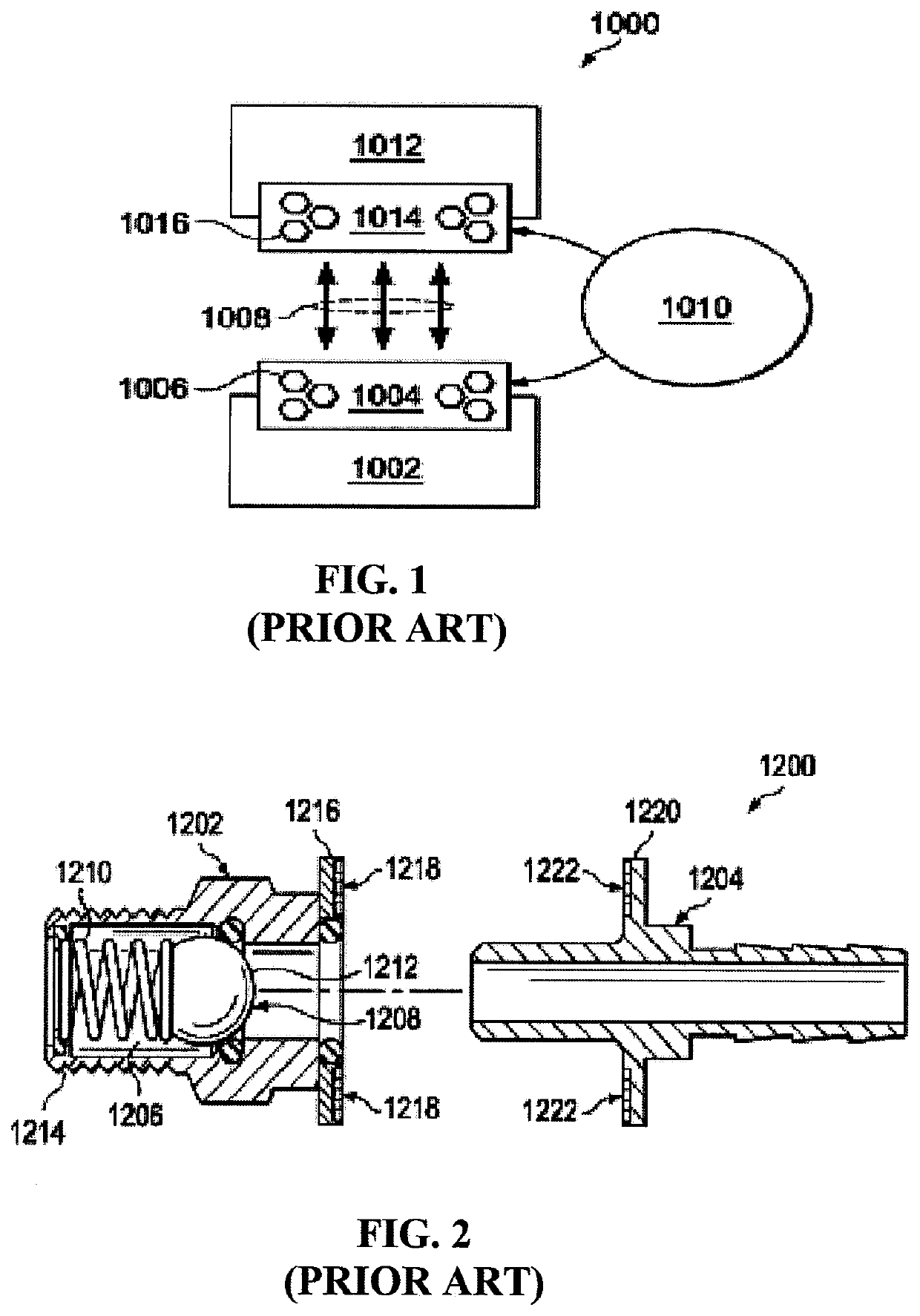
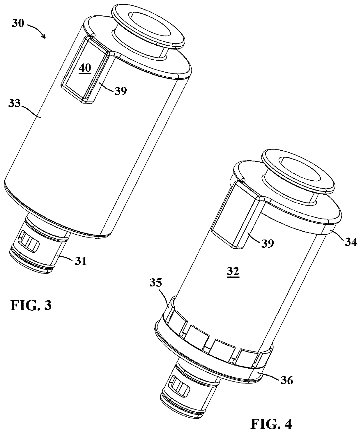
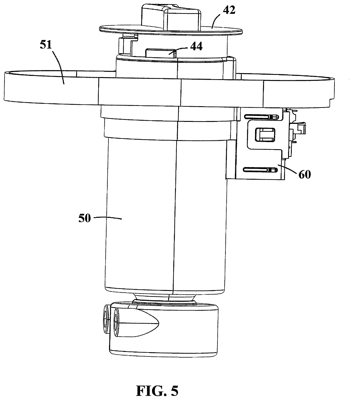
[0085]In describing the embodiments of the present invention, reference will be made herein to FIGS. 1-34 of the drawings in which like numerals refer to like features of the invention.

[0086]Certain terminology is used herein for convenience only and is not to be taken as a limitation of the invention. For example, words such as “upper,”“lower,”“left,”“right,”“front,”“rear,”“horizontal,”“vertical,”“upward,”“downward,”“clockwise,”“counterclockwise,”“longitudinal,”“lateral,” or “radial”, or the like, merely describe the configuration shown in the drawings. Indeed, the referenced components may be oriented in any direction and the terminology, therefore, should be understood as encompassing such variations unless specified otherwise. For purposes of clarity, the same reference numbers may be used in the drawings to identify similar elements.

[0087]Additionally, in the subject description, the words “exemplary,”“illustrative,” or the like, are used to mean serving as an example, instanc...


PUM

PropertyMeasurementUnit
Flow rateaaaaaaaaaa
Magnetic fieldaaaaaaaaaa

Abstract

A filtration system interconnection structure having a filter manifold including a sump housing and a first correlated magnet located on or connected to a portion of the manifold, and a filter cartridge including a filter media, first and second end caps sealed to the filter media, and a second, paired correlated magnet located on or connected to the filter cartridge housing body. The first and second correlated magnets are interconnected via magnetic communication upon insertion of the filter cartridge into the sump housing, and upon movement of the filter cartridge into an alignment position, the correlated magnet located on or connected to the manifold is permitted to translate as a result of the magnetic communication. The polarity profiles of the paired correlated magnets are aligned such that a repulsion force is created when the filter cartridge is inserted within the manifold sump housing.

Description

BACKGROUND OF THE INVENTION1. Field of the Invention[0001]The present invention relates to the interconnection scheme between a filter cartridge and its corresponding manifold. The invention utilizes a correlated magnetism design that encompasses correlated magnets, and more specifically a magnetic attraction, repulsion, or combination thereof to generate shear force, is introduced upon filter cartridge insertion into a mating manifold to aid in interconnection. In exemplary aspects, the interconnection scheme utilizes magnetic repulsion to aid in filter cartridge installation and / or removal. The function of the correlated magnetism in the present invention is at least two-fold: first, an upstream valve is actuated during initial installation of a filter cartridge into a mating manifold through non-electronic and non-contact actuation of a switch, and second, a magnetic repulsion force is introduced upon rotation to assist in filter cartridge removal from the manifold.2. Description...

Claims


Application Information

Patent Timeline
IPC IPC(8): B01D35/30B01D29/31
CPCB01D2201/301B01D2201/4092B01D35/306B01D2201/4069B01D29/31B01D2201/16B01D2201/291B01D35/06B01D2201/4023B01D2201/4053B01D29/96B01D2201/303H01H36/0073H01H2036/0093B01D2201/4015B01D2201/52B03C1/02B03C2201/22H01H3/503
Inventor ASTLE, ROBERTLI, WILLIAMMORGAN, JASONSTRANDEMO, GARETTHARTMANN, MATTHEW W.
Owner KX TECH LLC (DW US)
Why Eureka
Try Eureka