
Waterproof electronic decoy technology

a technology of electronic decoys and decoys, which is applied in the field of decoy apparatuses and methods, spinning or flapping decoys, etc., can solve the problems of degrading the quality of the degrading the quality of the imitation body features of the decoy species, and being constructed of commonly used plastics

Pending Publication Date: 2020-12-10
NOE TIM
View PDF2 Cites 1 Cited by
  • Summary
  • Abstract
  • Description
  • Claims
  • Application Information

AI Technical Summary

Benefits of technology

The present invention is a practical and efficient waterfowl or migratory bird decoy for hunting purposes. The methods of manufacture and use are effective and reliable, and it is believed to fulfill a need and improve over the background technology.

Problems solved by technology

Existing decoys are believed to have significant limitations and shortcomings.
One problem for motorized moving wing decoys is that the power and motor mechanisms disposed inside decoy bodies are accessed through a cover or door placed on the top of the decoy body.
This exposes the power and motor mechanisms to moisture from rain, other precipitation, wave action, and the like, and to dust and dirt in the environment.
Another problem with top mounted access panels is that they present break lines that degrade the quality of the imitation body features of the decoy species.
This is particularly a problem for bodies constructed of commonly used plastics.
Commonly used plastics, although inexpensive to use, limit the quality of imitation ornamentation.
Other problems exist with respect to mounting of decoys on stakes or other bases, and to inferior control mechanisms and features, particularly remote control features.

Method used


Image

  • Waterproof electronic decoy technology
  • Waterproof electronic decoy technology
  • Waterproof electronic decoy technology

Examples


Embodiment Construction

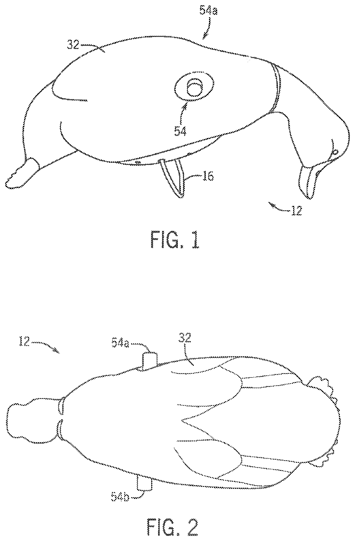
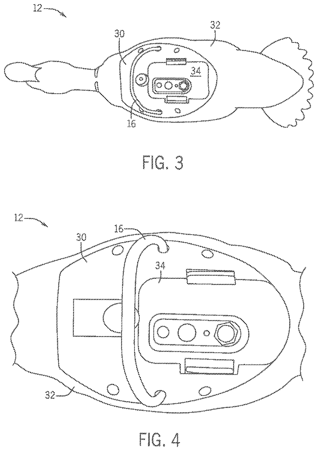
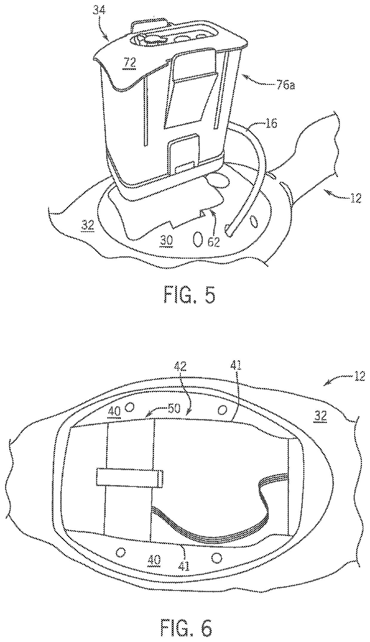
[0044]Referring to FIGS. 1 and 2, one embodiment of the decoy set 10 of the invention includes a waterproof decoy 12 and a mounting base 14. The decoy 12 embodiment simulates a waterfowl or migratory bird, particularly in this embodiment, a duck (most particularly a mallard). The decoy 12 is coupled to the base 14 by a friction fit type, insert connection (female type in the decoy 12 and male type for the base 14) between the top of the base 14 and the bottom of the decoy 12. Preferably, the set 10 includes a stabilizer 16, most preferably a biased stabilizer cord. The embodiment of the base 14 is a post or stake which has a vertical member 18 with a top 20 and a bottom 22 and a horizontal member 24 that forms a T type configuration. The bottom end 22 may be configured as a spike to pierce the earth, for example the submerged bottom of a lake, pond, marsh or the like. The T type configuration forms a handle at the top of the base 24 to facilitate easier manual pushing during placeme...


PUM


Abstract

A waterproof moving wing waterfowl or migratory bird decoy including a decoy body constructed of a waterproof, polymeric with exterior ornamentation to simulate a live waterfowl or migratory bird, the decoy body being arranged in a predetermined orientation to simulate a waterfowl or migratory bird, the decoy body having a top and a bottom. The decoy has at least one decoy wing connected to the decoy body, the decoy wing being constructed and arranged to simulate the wing of a waterfowl or migratory bird. The decoy has a power and control module, the power and control module being connectible and dis-connectible to the decoy body at the bottom of the decoy body, the power and control module actuating the at least one decoy wing, the power and control module including a waterproof housing having a door enclosing a cavity, a battery disposed within the housing cavity, and an electronic control assembly communicatively connected to the battery and disposed within the housing cavity.

Description

CROSS-REFERENCE TO RELATED APPLICATIONS, IF ANY[0001]This application claims the benefit under 35 U.S.C. § 119(e) of co-pending U.S. Provisional Patent Application Ser. No. 62 / 795,285, filed Jan. 22,2019, which is hereby incorporated by reference.37 C.F.R. § 1.71(e) AUTHORIZATION[0002]A portion of the disclosure of this patent document contains material which is subject to copyright protection. The copyright owner has no objection to the facsimile reproduction by anyone of the patent document or the patent disclosure, as it appears in the US Patent and Trademark Office patent file or records, but otherwise reserves all copyright rights whatsoever.STATEMENT REGARDING FEDERALLY SPONSORED RESEARCH OR DEVELOPMENT[0003]Not applicable.REFERENCE TO A MICROFICHE APPENDIX, IF ANY[0004]Not applicable.BACKGROUND OF THE INVENTION1. Field of the Invention[0005]The present invention relates, generally, to hunting systems, apparatus and methods. More particularly, the invention relates to a decoy ...

Claims


Application Information

Patent Timeline
IPC IPC(8): A01M31/06
CPCA01M31/06
Inventor NOE, TIM
Owner NOE TIM
Learn More