Dynamic Pumpjack Load Verification

a pumpjack and load verification technology, applied in the direction of instruments, borehole/well accessories, construction, etc., can solve the problems of inaccurate calculation of downhole cards, unobserved surface load calibration in practice, and correlation between diagonal card locations, so as to facilitate the diagnosis of fluid density and accurately diagnose the operation of running wells.

Active Publication Date: 2020-12-10
PHILLIPS WALTER
View PDF0 Cites 1 Cited by
  • Summary
  • Abstract
  • Description
  • Claims
  • Application Information

AI Technical Summary

Benefits of technology

[0012]A similar effect of this diagonal shifting of calculated downhole load and position occurs when mechanical sliding friction acts along the rod-string. In this case, the measured surface loads are correct, but some additional force is added during the up-stroke (and subtracted on the down-stroke). One could consider this as a more general case of the miscalibrated load-cell, specifically in the context of the calculated downhole conditions. The miscalibrated load-cell gives an incorrect input to the wave equation, yielding an incorrectly calculated downhole card. In the case of downhole friction, the surface load is correctly measured, but the existing implementations of the wave equation do not adequately address and remove the friction induced tensile forces, and so the calculated downhole card is also incorrect. This is the so-called Gibbs' Conjecture and is discussed briefly below.
[0013]Another key parameter of interest in the wave equation is fluid density, which directly affects the weight of the rods, which are submerged in that fluid. If this fluid density parameter is incorrect, the expected static weight of the rods will also be incorrect. The dynamically calculated forces will then be based on erroneous static rod-loading and thus the calculated downhole pump card will be shifted, again, on a distinct and identifiable diagonal. Unlike friction, this buoyancy effect is independent of direction of travel. Once identified, it can be relatively easy to diagnose fluid density through established methodologies.
[0014]Incorrect tubing and / or casing pressure will alter the loads seen at surface. Similarly, fluid level in the casing annulus will impact the measured loads seen at surface. In these cases, the altering force is only present during the up-stroke, as those loads only contribute to the fluid load on the pump while lifting fluid to surface. During the down-stroke, no fluid is lifted and so the net force acting on the pump plunger is effectively zero. While these are real forces, it is desirable to account for them to accurately diagnose the operation of a running well. While this method may not distinguish casing / tubing pressure from fluid level effects, it can identify unexpected loads during a specific pump state. This enables the method disclosed herein to flag those parameters as possibly incorrect. Identification of possible errors allows the operator to further diagnose the set of input parameters.

Problems solved by technology

Unfortunately, in artificially shifting the pump cards to zero position, this diagonal shifting phenomenon and correlation between diagonal card location, and surface load calibration has remained unobserved in practice.
In the case of downhole friction, the surface load is correctly measured, but the existing implementations of the wave equation do not adequately address and remove the friction induced tensile forces, and so the calculated downhole card is also incorrect.
If this fluid density parameter is incorrect, the expected static weight of the rods will also be incorrect.

Method used


Image

  • Dynamic Pumpjack Load Verification
  • Dynamic Pumpjack Load Verification
  • Dynamic Pumpjack Load Verification

Examples


Embodiment Construction

Definitions

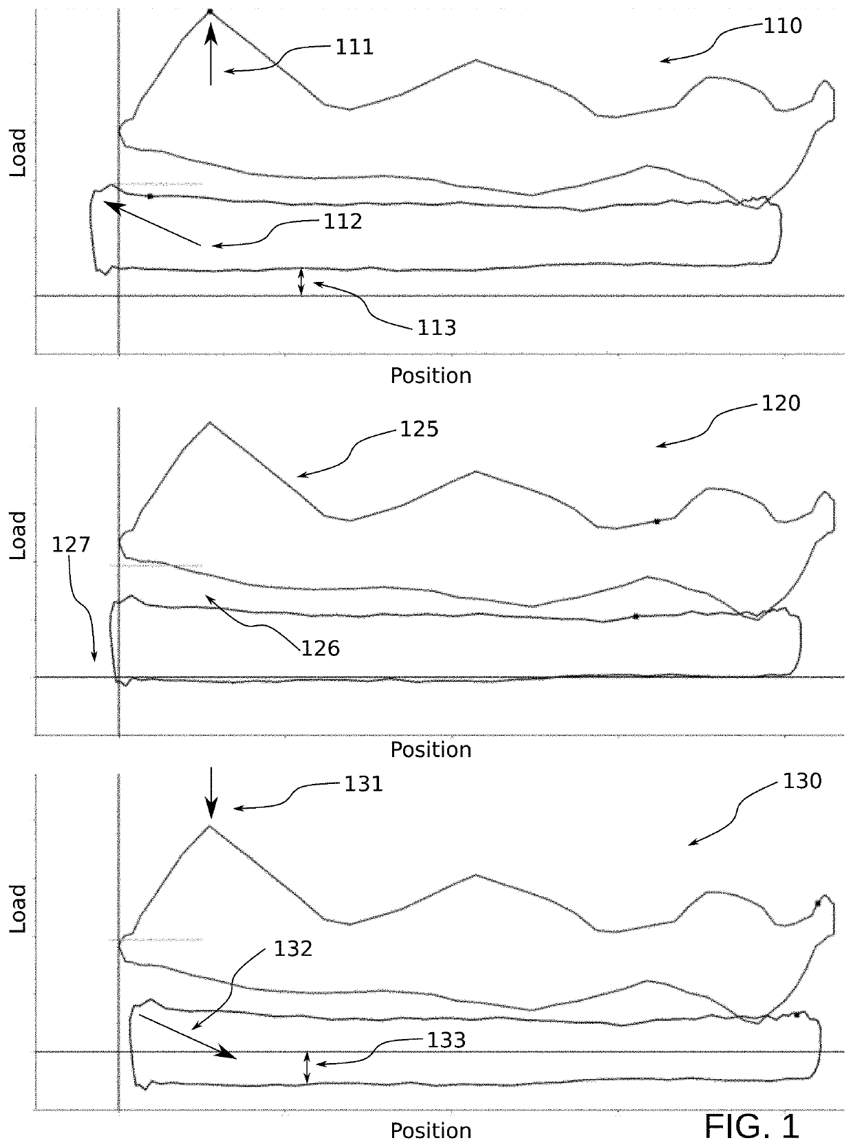
[0023]The dyno (or dynamometer) card refers to the common plot of load vs. position for a single stroke of the pumping system. Dyno cards are gathered at surface from measured load and position. The downhole pump card (and at arbitrary depths along the rod-string) is calculated through a mathematical method commonly referred to as the “wave equation”, described below.

[0024]The well controller refers to an existing industrial well control system. These are often referred to in the industry as a pump-off controller (POC). Pump-off controllers are responsible for digitizing load and position measurements and controlling the operation of the well. This includes safety shutdowns based on load thresholds but can also include “normal” shutdowns due to operational conditions. The “pumped off” condition refers to the state of the down-hole pump, where the fluid displaced by the pump exceeds the inflow from the reservoir. The pump then does not have sufficient fluid for a full pump...


PUM

PropertyMeasurementUnit
elasticityaaaaaaaaaa
pressuresaaaaaaaaaa
surface loadsaaaaaaaaaa

Abstract

A properly calibrated load-cell is critical for the safe operation of a rod-pumping system. Load readings are utilized for shutdown thresholds, and incorrect measurements can cause those safe load limits to be exceeded. Correct surface load, combined with position measurement, is also important for the diagnosis of the complete pumping system. The diagnostic method for calculating down-hole conditions presents an interesting opportunity to validate surface load measurements, even from the incorrect load measurements themselves. The calculated down-hole dynamometer card will be transposed on a distinct diagonal with respect to both load and position, if the input surface load measurements are incorrect. A load offset can then be identified from this shifting and the surface load measurements can be corrected. Calculated pump cards have been traditionally aligned with the surface dyno card position, and so this diagonal pump card shifting correlation with incorrect, or unexpected, surface load has not been realized.

Description

BACKGROUND OF THE INVENTION[0001]This section is intended to introduce various aspects of the art, which may be associated with exemplary embodiments of the present disclosure. This discussion is believed to assist in providing a framework to facilitate a better understanding of particular aspects of the present disclosure. Accordingly, it should be understood that this section should be read in this light, and not necessarily as admissions of prior art.FIELD OF THE INVENTION[0002]The present disclosure relates to the field of hydrocarbon recovery operations. More specifically, the present invention relates to the production of fluids to the surface using rod pumping equipment. The invention also relates to a method for validating and calibrating a load-cell signal during the operation of the rod-pumping system. More generally, the method can identify incorrect or unexpected loads. Specifically, it utilizes dynamic calculations known commonly as the wave equation to determine pump c...

Claims


Application Information

Patent Timeline
Patent Type & Authority Applications(United States)
IPC IPC(8): E21B47/009E21B43/12G01L5/00
CPCG01L5/0061E21B47/009E21B43/127
Inventor PHILLIPS, WALTER
Owner PHILLIPS WALTER
Why Eureka
Try Eureka