Power conversion device and manufacturing method thereof

which is applied in the direction of power conversion system, power conversion device details, cooling/ventilation/heating modification, etc., can solve the problems of increasing the size and insufficient amount of pressurizing force applied to the stacked body, etc., to achieve the effect of improving the spring characteristics of the first frame serving as a spring member, reducing the size of the case, and reducing the size of the a power conversion device and manufacturing method of power conversion device and manufacturing method of power conversion device and manufacturing method of power conversion device and manufacturing method, a technology of power conversion device and manufacturing method, which is applied in the field of power conversion device and manufacturing method, which is applied in the field of power conversion device and manufacturing method, which is applied in the power conversion device the effect of the power conversion device and the effect of the entire first frame, the a technology of power conversion device and manufacturing method, which is applied in the field of power conversion device and manufacturing method, which is applied in the field

Active Publication Date: 2020-12-10
DENSO CORP
View PDF0 Cites 2 Cited by
  • Summary
  • Abstract
  • Description
  • Claims
  • Application Information

AI Technical Summary

Benefits of technology

[0013]In the second aspect, the manufacturing method may further include a step of installing a load receiver on an outside of the abutting wall before the step of pressurizing. During the step of pressurizing, the pressurizing force applied to the stacked body may be increased to a second pressurizing force larger than the first pressurizing force, and then decreased to the first pressurizing force. With such a configuration, the grease-state TIM applied between the semiconductor module and the cooler adjacent to the semiconductor module can be spread in a relatively short time.
[0014]In the second aspect, during the step of pressurizing, the pressurizing force applied to the stacked body may be increased to a third pressurizing force larger than the first pressurizing force such that plastic deformation occurs in a bent portion of the first frame, and then decreased to the first pressurizin...

Problems solved by technology

Therefore, it also leads to an increase in the size of the case, that is, an increase in the size of the power conversion device.
However, since there is no spring mem...

Method used


Image

  • Power conversion device and manufacturing method thereof
  • Power conversion device and manufacturing method thereof
  • Power conversion device and manufacturing method thereof

Examples


Embodiment Construction

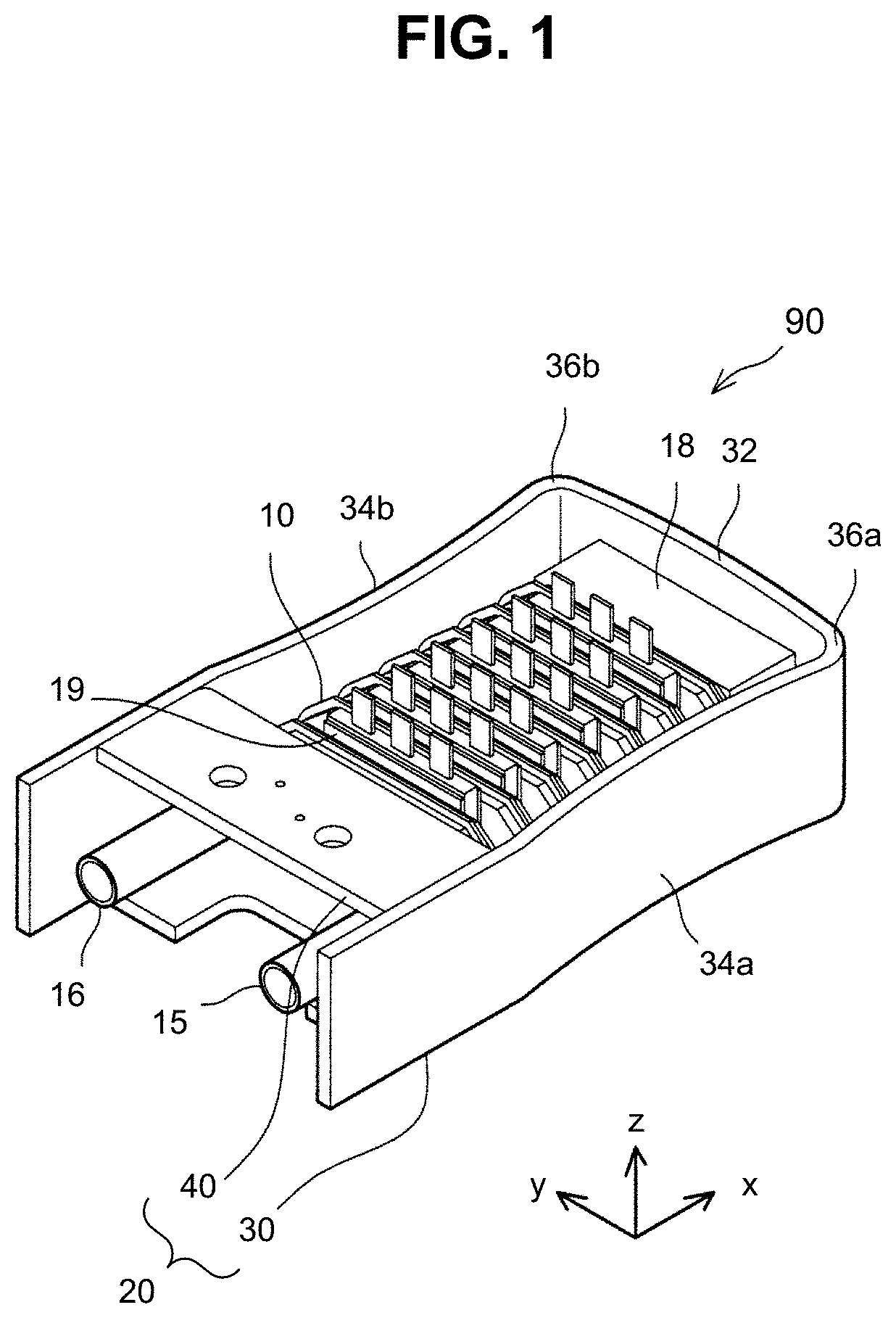
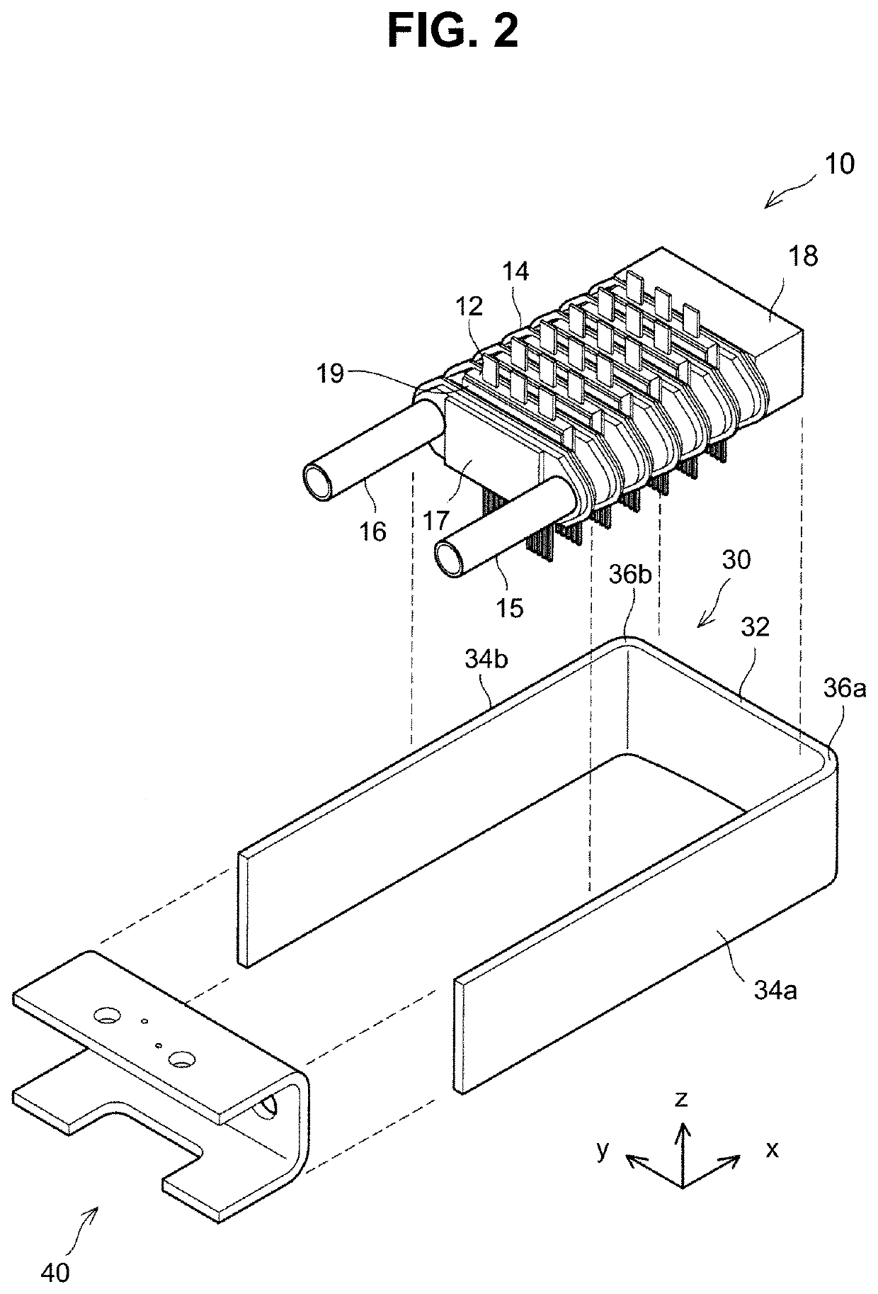
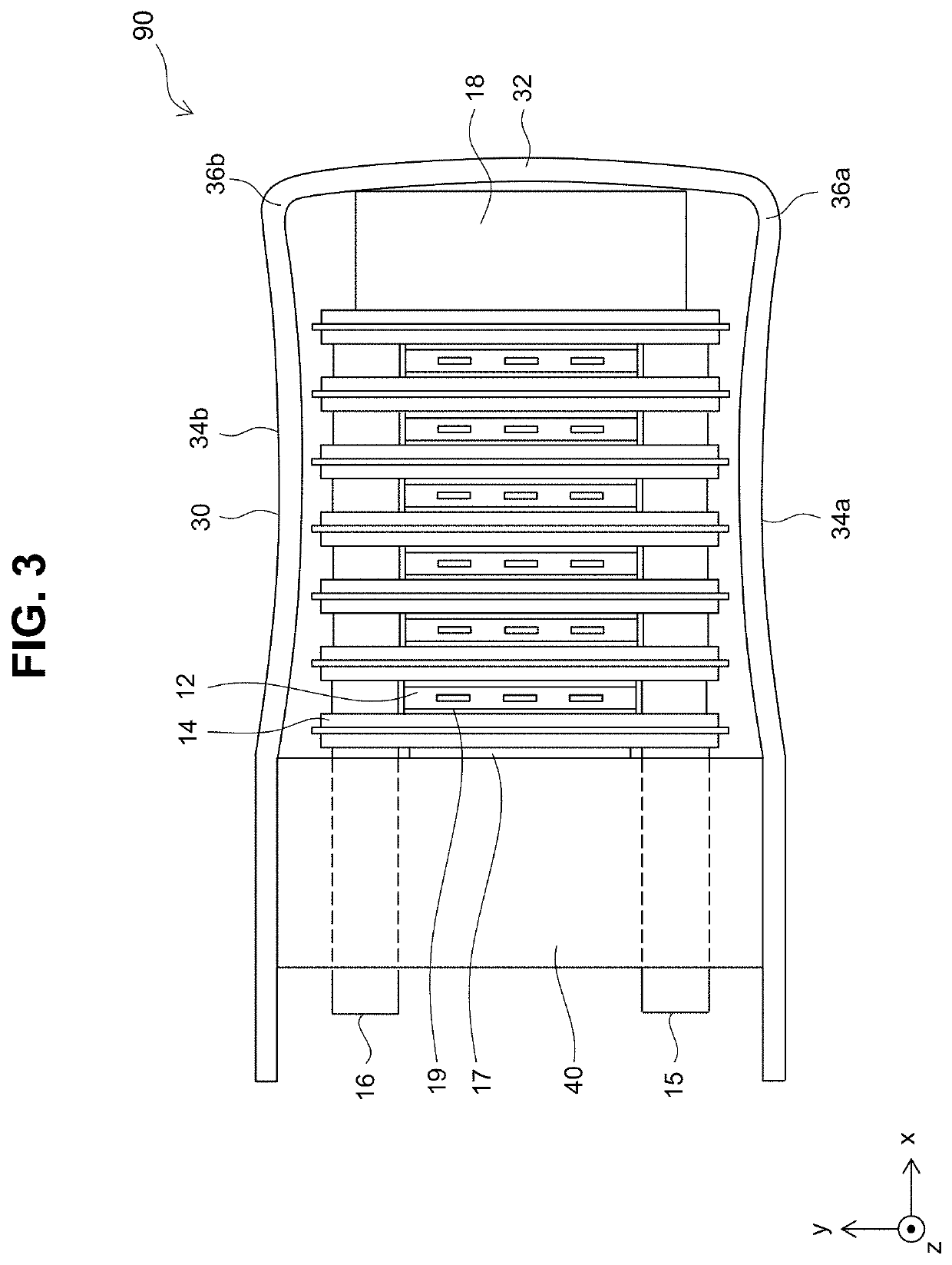
[0028]A power conversion device 90 according to an embodiment will be described with reference to the drawings. The power conversion device 90 according to the embodiment performs power conversion between a power source and a load. The power conversion device 90 may be mounted on, for example, an electric vehicle, but is not limited thereto, and can be used as a power conversion device for various applications. As illustrated in FIG. 1, the power conversion device 90 includes a stacked body 10 and a frame 20. The stacked body 10 is pressurized and held by the frame 20.

[0029]As illustrated in FIGS. 2 and 3, the stacked body 10 is a unit in which the semiconductor modules 12 and the coolers 14 are alternately stacked. The semiconductor module 12 is a device including a plurality of semiconductor elements (not shown) therein. The semiconductor element is for power conversion and is also referred to as a power semiconductor element. A large amount of heat is generated when high current ...


PUM


Abstract

A power conversion device includes a plurality of semiconductor modules, a plurality of coolers, and a frame. The frame pressurizes and holds a stacked body in which the semiconductor modules and the coolers are alternately stacked. The frame includes a first frame and a second frame that sandwich the stacked body therebetween. The first frame is a plate material bent to surround the stacked body from three directions, and includes a pair of side walls extending in the stacking direction of the stacked body, and an abutting wall extending between the side walls and abutting the stacked body. The abutting wall is bent outward from the frame. Each of the side walls is bent inward from the frame.

Description

CROSS-REFERENCE TO RELATED APPLICATION[0001]This application claims priority to Japanese Patent Application No. 2019-107238 filed on Jun. 7, 2019, incorporated herein by reference in its entirety.BACKGROUND1. Technical Field[0002]The technology disclosed in the present disclosure relates to a power conversion device and a manufacturing method thereof.2. Description of Related Art[0003]Japanese Unexamined Patent Application Publication No. 2012-257416 (JP 2012-257416 A) and Japanese Unexamined Patent Application Publication No. 2016-123147 (JP 2016-123147 A) describe a power conversion device in which a plurality of semiconductor modules and a plurality of coolers are alternately stacked. In these types of power conversion devices, it is necessary to pressurize and hold a stacked body of the semiconductor modules and the coolers in a stacking direction in order to increase adhesion between the semiconductor modules and the coolers. Thus, for example, in the power conversion device di...

Claims


Application Information

Patent Timeline
IPC IPC(8): H01L23/473H01L25/10H05K7/20
CPCH01L23/473H05K7/20927H01L25/105H01L23/367H01L23/40H01L21/02H01L21/67092H02M1/00H01L23/4012H01L2225/1094
Inventor MAEDA, TOMOYUKI
Owner DENSO CORP
Why Eureka
Try Eureka