Symbol-determining device and symbol determination method

a symbol determination and symbol technology, applied in the direction of error prevention, digital transmission, line-transmission details, etc., can solve the problems of inter-code interference, increase the speed of a system configuration using a low-cost device, and deterioration in signal quality accompanying an increase in transmission capacity, so as to achieve the effect of increasing the amount of calculation

Active Publication Date: 2020-12-10
NIPPON TELEGRAPH & TELEPHONE CORP
View PDF0 Cites 1 Cited by
  • Summary
  • Abstract
  • Description
  • Claims
  • Application Information

AI Technical Summary

Benefits of technology

[0028]According to the present invention, a symbol determination method using MLSE inhibiting an increase in the amount of calculation can be provided.

Problems solved by technology

As a problem with respect to a further increase in capacity, there is deterioration in a signal quality accompanying an increase in transmission capacity.
More specifically, there is inter-code interference due to band limitation accompanying an increase in the speed of a system configuration using a low-cost device, in other words, a narrow-band device.
Therefore, when the estimation accuracy becomes high, code errors due to inter-code interference can be inhibited.

Method used


Image

  • Symbol-determining device and symbol determination method
  • Symbol-determining device and symbol determination method
  • Symbol-determining device and symbol determination method

Examples


first embodiment

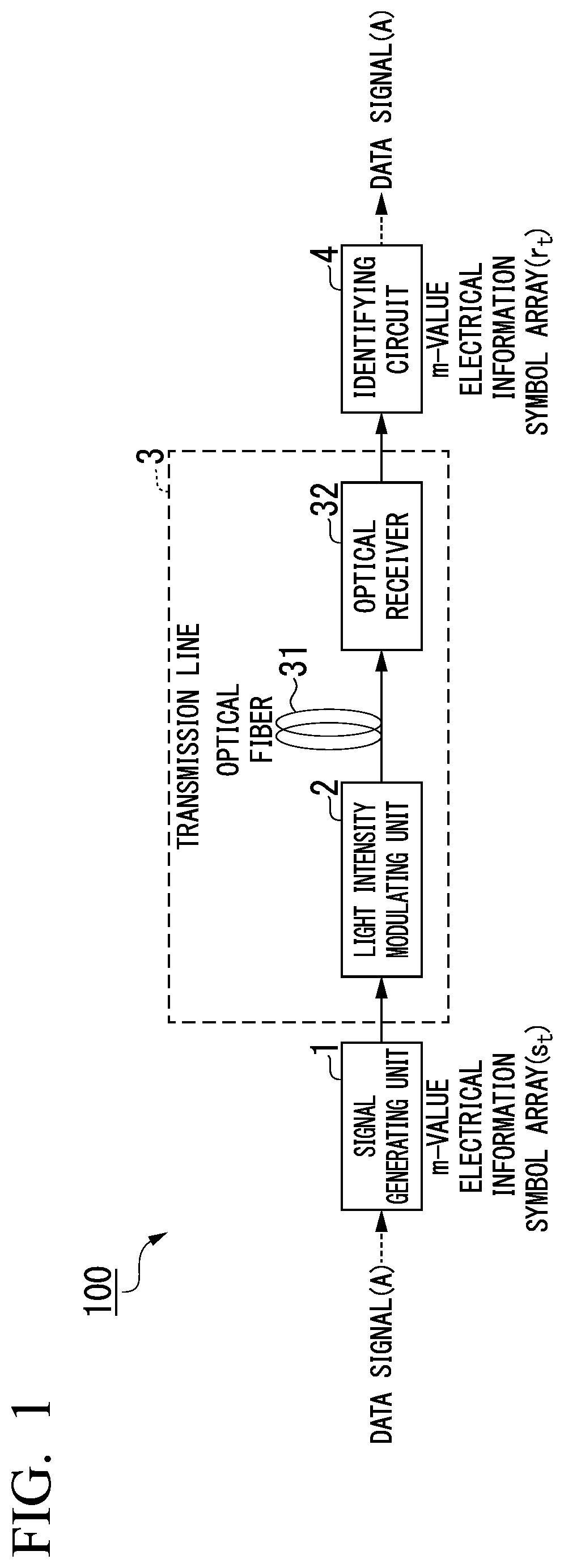
[0041]FIG. 1 is a diagram illustrating a specific system configuration of a communication system 100 according to a first embodiment. The communication system 100 is an optical transmission system that transmits information represented by a symbol array.

[0042]The communication system 100 includes a signal generating unit 1, a light intensity modulating unit 2, a transmission line 3, and an identifying circuit 4 (a symbol-determining device).

[0043]The signal generating unit 1 generates an electrical information symbol array of m values (hereinafter, referred to as an “an m-value electrical information symbol array”) {st} from an input data signal. The m-value electrical information symbol array represents m-ary codes. One symbol of the m-value electrical information symbol array represents m kinds of signs (or numbers) according to the magnitude of a voltage or a current. Here, m is an integer that is equal to or larger than 2 and is a degree of multiple values of a symbol. When m ki...

second embodiment

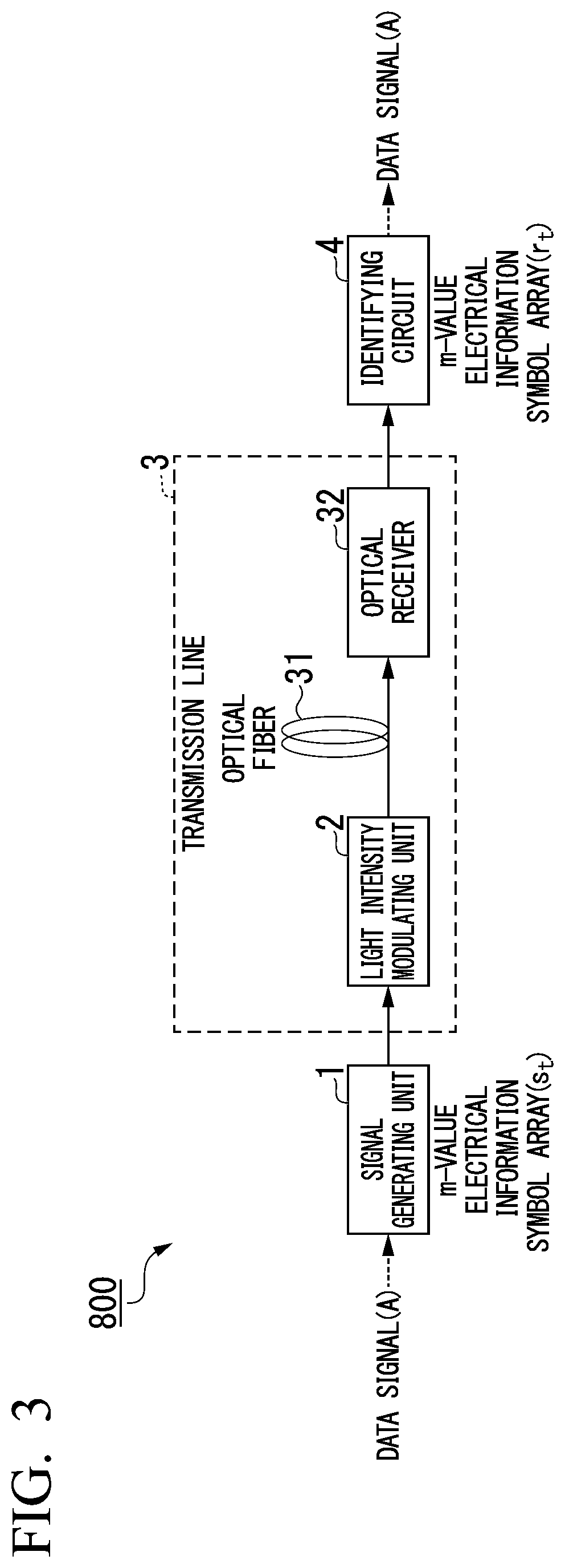
[0103]FIG. 9 is a diagram illustrating a specific system configuration of a communication system 100a according to a second embodiment. The communication system 100a includes an identifying circuit 4a instead of the identifying circuit 4, which is different from the communication system 100. Hereinafter, the same reference signs as those illustrated in FIG. 1 are assigned to units having the same functions, and description thereof will be omitted.

[0104]The identifying circuit 4a, similar to the identifying circuit 4, acquires an m-value electrical information symbol array {rt} and performs symbol determination of acquiring an estimated value of each symbol of the m-value electrical information symbol array {st}.

[0105]FIG. 10 is a diagram illustrating a specific example of the functional configuration of the identifying circuit 4a according to the second embodiment. The identifying circuit 4a includes a first filter update algorithm unit 47a (filter updating unit) and a second filter...

modified example

[0110]In addition, in the communication system 100 according to the first embodiment and the communication system 100a according to the second embodiment, by configuring the transmission line shortening unit 41 and the first transmission line estimating unit 42 as adaptive digital filters, symbol determination using blind estimation without requiring prior tap gain training can be performed. In such a case, in order to normally operate the adaptive digital filter, it is necessary that the tap coefficients and the Volterra kernel be accurately performed.

[0111]In addition, as a characteristic of an optical transmission line, variation speeds of factors of wavelength distortion (a band limit and a wave dispersion) are very slow. For this reason, as superiority of photoelectric field sequential estimation, by configuring the transmission line shortening unit 41 and the first transmission line estimating unit 42 as adaptive digital filters and performing tap gain training in advance, the...


PUM


Abstract

A symbol-determining device according to an embodiment includes: a transmission line shortening unit that multiplies each symbol value of a symbol array that is part of an input signal by a tap gain of a linear digital filter and outputs a symbol array representing a sum of values acquired through the multiplication; a transmission line estimating unit that estimates a transfer function of a transmission line using an adaptive nonlinear digital filter on the basis of a symbol array representing a state of the transmission line; an addition comparison processing unit that calculates a minimum value of a distance function in a Viterbi algorithm on the basis of a metric that is calculated on the basis of the output of the transmission line shortening unit and the transfer function; and a path tracing-back determination unit that performs symbol determination by tracing back a trellis path in the Viterbi algorithm on the basis of the minimum value of the distance function.

Description

TECHNICAL FIELD[0001]The present invention relates to a symbol-determining device and a symbol determination method.[0002]Priority is claimed on Japanese Patent Application No. 2018-007671, filed Jan. 19, 2018, the content of which is incorporated herein by reference.BACKGROUND ART[0003]In accordance with the rapid spread of smartphones and tablets and an increase in rich contents such as high-definition moving image delivery services and the like in recent years, traffic transmission through a backbone network such as the Internet is continuously increasing. In addition, as the utilization of cloud services advances in companies, network traffic between DCs and inside data centers (DCs) is also predicted to increase at a rate of about 1.3 times per year likewise. Currently, in a connection system inside a DC or between DCs, Ethernet (a registered trademark; hereinafter the same) has been mainly introduced. In accordance with an increase in communication traffic, it is predicted tha...

Claims


Application Information

Patent Timeline
Patent Type & Authority Applications(United States)
IPC IPC(8): H04B3/06H04B10/69H04L1/00
CPCH04L1/0054H04B3/06H04B10/697H03M13/41H04B10/6971H04L25/03019H04L25/03203H04L25/03184H04L25/03178
Inventor TANIGUCHI, HIROKIYAMAMOTO, SHUTOMASUDA, AKIRAFUKUTOKU, MITSUNORI
Owner NIPPON TELEGRAPH & TELEPHONE CORP
Why Eureka
Try Eureka