

Visibility of Mechanical Thrombectomy Device During Diagnostic Imaging
a technology of mechanical thrombus and diagnostic imaging, which is applied in the field of endovascular medical system, can solve the problems of relatively poor visibility and relatively low radiopacity of mechanical thrombus under fluoroscopic imaging, and achieve the effect of improving visibility
- Summary
- Abstract
- Description
- Claims
- Application Information
AI Technical Summary
Benefits of technology
Problems solved by technology
Method used
Image

Examples
Embodiment Construction
[0055]The terms “distal” or “proximal” are used in the following description with respect to a position or direction relative to the treating physician or medical interventionalist. “Distal” or “distally” are a position distant from or in a direction away from the physician or interventionalist. “Proximal” or “proximally” or “proximate” are a position near or in a direction toward the physician or medical interventionalist. The terms “occlusion”, “clot” or “blockage” are used interchangeably.
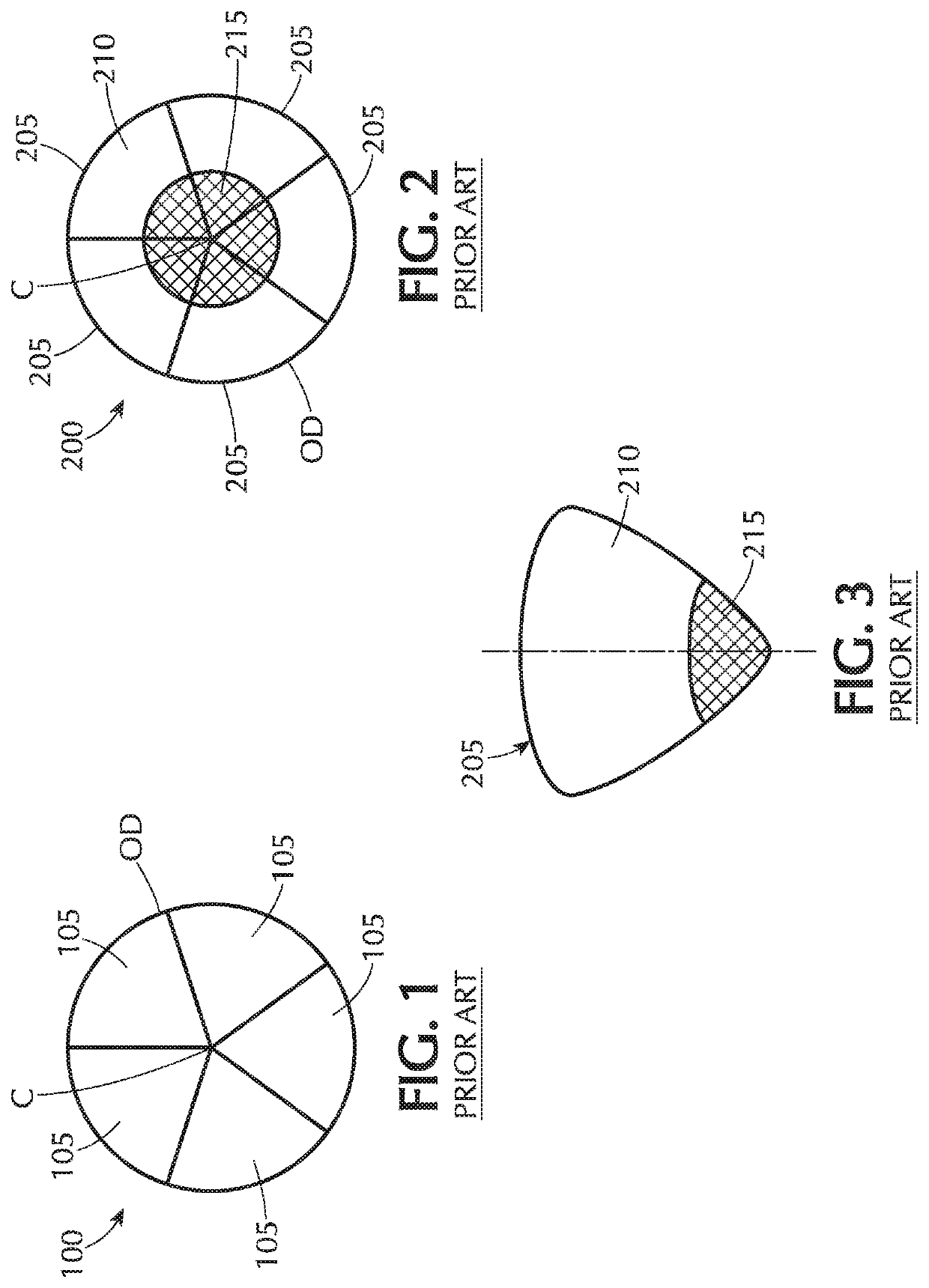
[0056]Referring to FIG. 2, a radial cross-sectional view of an exemplary Prior Art drawn filled tube (DFT) composite wire 200 to produce a mechanical thrombectomy device is illustrated. The wire in FIG. 2 has an inner core 215 made of a first biocompatible material surrounded by an outer layer 210 of a second biocompatible material that differs from the first material. The first material forming the inner core 215 is made of a radiopaque material, that is, a material that is opaque to one or ano...
PUM
 Abstract
Description
Claims
Application Information