Cranial surgery using optical shape sensing

Active Publication Date: 2020-12-17
KONINKLJIJKE PHILIPS NV
View PDF0 Cites 4 Cited by
  • Summary
  • Abstract
  • Description
  • Claims
  • Application Information

AI Technical Summary

Benefits of technology

[0010]As integrated optical shape sensors and as segregated optical shape sensors, the mask registration shape of the mask optical shape sensor and the tool registration

Problems solved by technology

The procedure has historically often been accomplished using a freehand technique, which is not optimal.
Often multiple attempts are needed, which results in unnecessary neurological damage.
However, the drain/shunt placement tool typically has a thin diameter (e.g., a metallic inner stylet typically has a 1 millimeter diameter), which frequently results in a bending of the drain/shunt placement tool whereby the optical navigation of the drain/shunt experiences inaccurate tracking of the tool due to a false assumption of a straight

Method used


Image

  • Cranial surgery using optical shape sensing
  • Cranial surgery using optical shape sensing
  • Cranial surgery using optical shape sensing

Examples


Embodiment Construction

[0033]The present disclosure is applicable to numerous and various forms of cranial surgical applications as known in the art of the present disclosure and hereinafter conceived including, but not limited to, numerous and various forms of ventriculostomy external ventricular drain via catheters and permanent shunts.

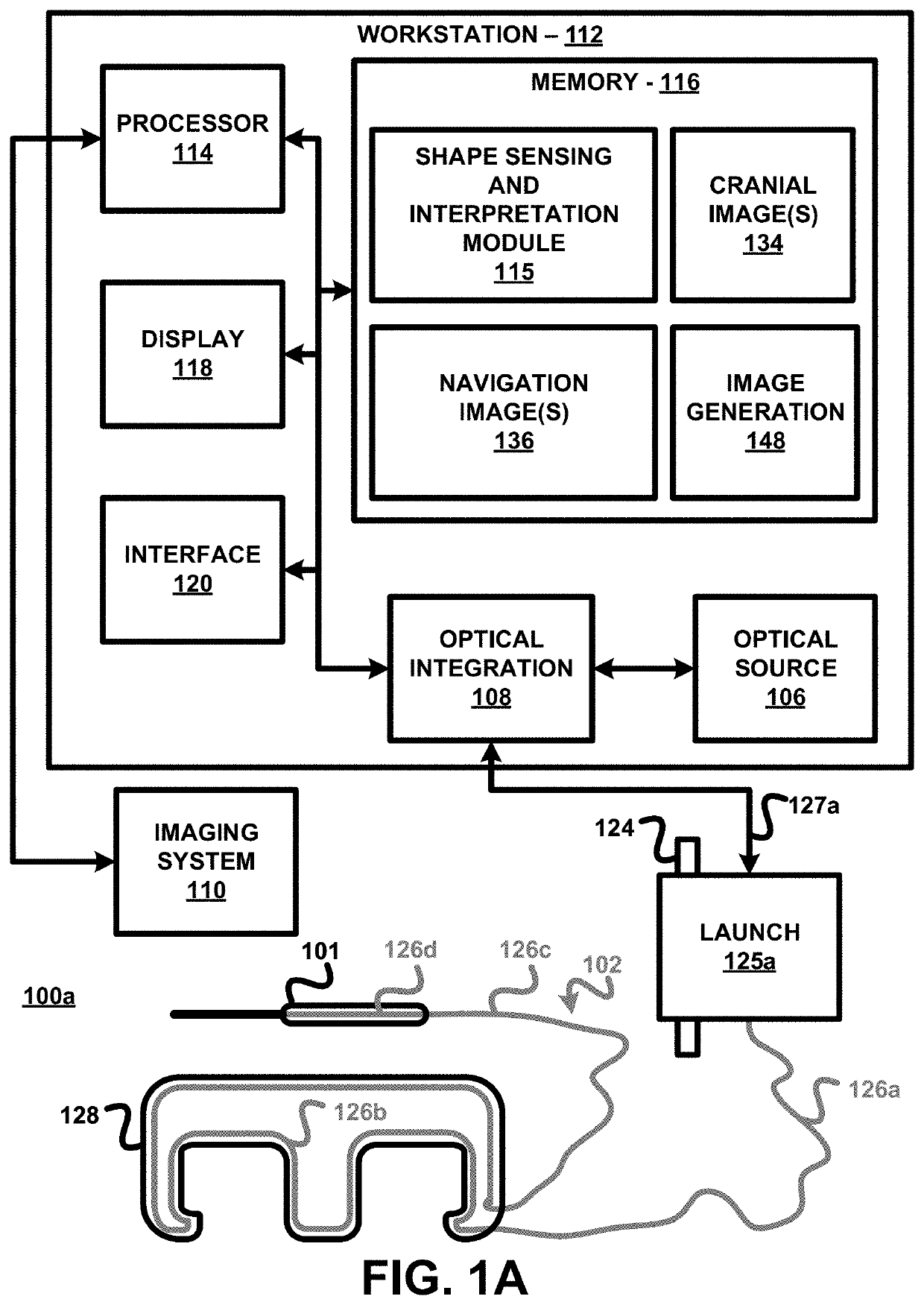
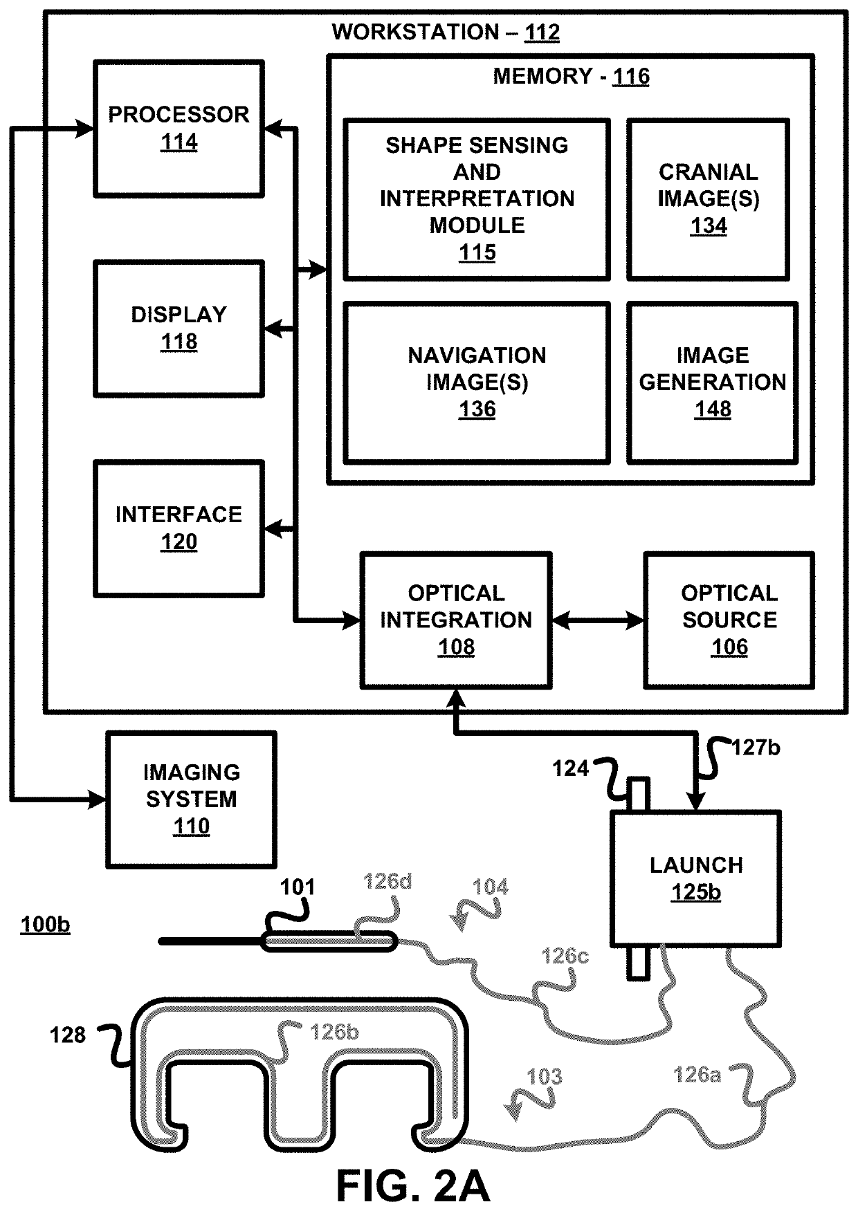
[0034]The present disclosure employs optical shape sensing technology in cranial surgical procedures as an improvement over the prior art of a combination of EM-optical tracking of cranial surgery tools, such as, for example, a EM-optical tracking of a placement of drains / shunts within a cerebral ventricle.

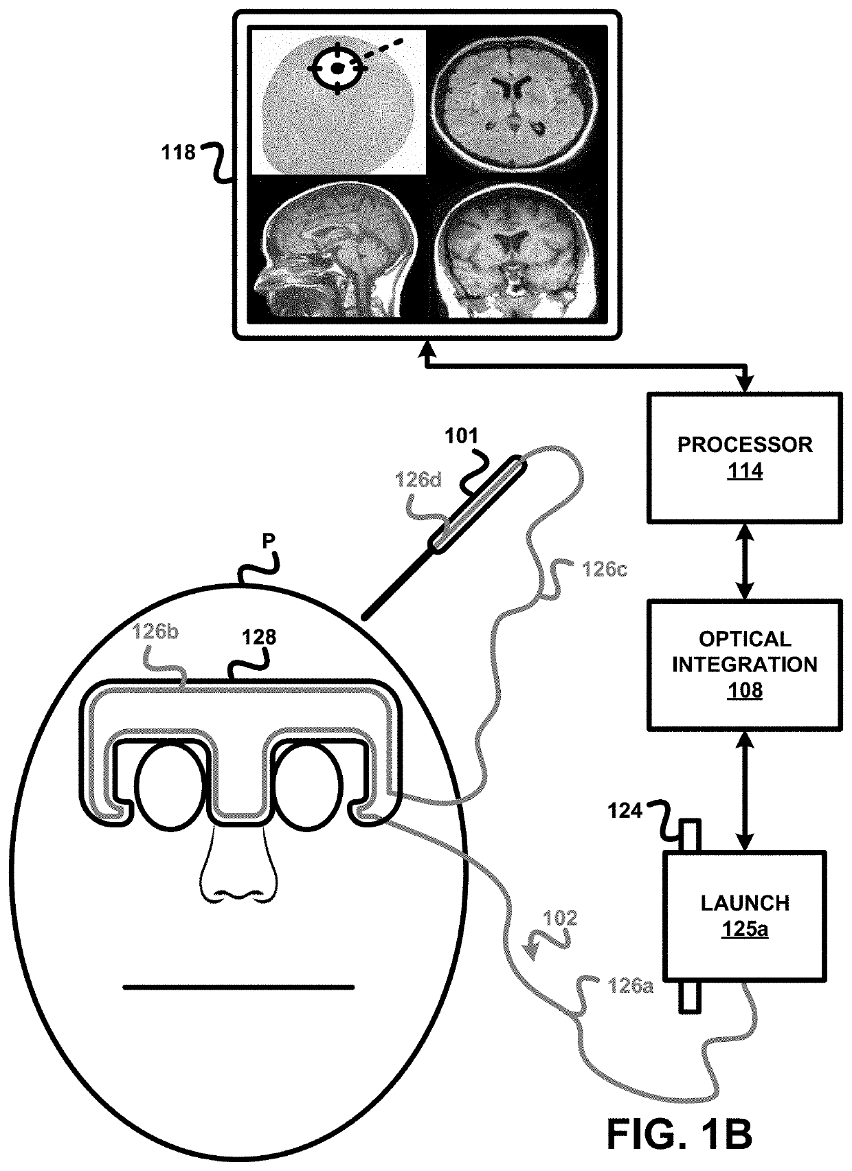
[0035]More particularly, in accordance with the present principles, devices, systems and methods are provided for optical shape sensing that can be used for spatially registering a cranial surgery tool (e.g., a ventricular drain stylet). In one embodiment of the present disclosure, the optical shape sensing employs shape sensing optical fiber(s) incorporated within cran...


PUM


Abstract

Various cranial surgery OSS registration device embodiments of the present disclosure encompass a cranial surgery facial mask (128), a mask optical shape sensor (126b) having a mask registration shape extending internally within the cranial surgery facial mask (128) and/or externally traversing the cranial surgery facial mask (128), a cranial surgery tool (101), and a tool optical shape sensor (126d) having a tool registration shape extending internally within the cranial surgery tool (101) and/or externally traversing the cranial surgery tool (101). The mask registration shape of the mask optical shape sensor (126b) and the tool registration shape of the tool optical shape sensor (126d) interactively define a spatial registration of the cranial surgery facial mask (128) and the cranial surgery facial mask (128) and the cranial surgery tool (101) to a cranial image.

Description

FIELD OF THE INVENTION[0001]The present disclosure generally relates to cranial surgery (e.g., ventricular drain / shunt placement). The present disclosure specifically relates to utilization of optical shape sensing (OSS) technology to improve cranial surgery, particularly ventricular drain / shunt placement.BACKGROUND OF THE INVENTION[0002]Ventricular drain / shunt placement from the lateral ventricles of the brain is one of the most common neurological interventions and has high reimbursement. The procedure has historically often been accomplished using a freehand technique, which is not optimal. Often multiple attempts are needed, which results in unnecessary neurological damage. To improve upon the freehand technique, navigated ventricular drain / shunt placements solutions exist that rely on optical navigation, which is often combined with electromagnetic-based navigation.[0003]Specifically, optical navigation is used to register the patient to a pre-op computed tomography (CT) volume...

Claims


Application Information

Patent Timeline
IPC IPC(8): A61B34/20A61M27/00
CPCA61B34/20A61B2034/2061A61B2034/2055A61M27/006A61B2090/364A61B34/10A61B2034/2068A61B2034/107A61B2034/108A61B90/10A61B90/18A61B2034/105A61B2090/3966
Inventor HOLTHUIZEN, RONALDUS FREDERIK JOHANNESVERSTEGE, MARCOVAN DER STERREN, WILLIAM EDWARD PETER
Owner KONINKLJIJKE PHILIPS NV
Why Eureka
Try Eureka