Vehicle steering control method and vehicle steering control device

Active Publication Date: 2020-12-17
NISSAN MOTOR CO LTD
View PDF0 Cites 7 Cited by
  • Summary
  • Abstract
  • Description
  • Claims
  • Application Information

AI Technical Summary

Benefits of technology

The present invention aims to provide a method and device for controlling steering of a vehicle that can reduce the vibration of the steering wheel when engaging a clutch and prevent a feeling of discomfort for the driver. The method includes supplying an assist torque during autonomous driving mode but reducing it when transitioning to manual mode to prevent vibration of the steering wheel. This results in a more stable and comfortable driving experience.

Problems solved by technology

However, under circumstances in which an abnormal event has occurred, the clutch is placed in an engaged state in which the steering wheel and the turnable wheels are mechanically coupled to one another, and the turnable wheels are turned using steering force from the steering wheel.
However, the present inventors have discovered that the following problem occurs when, during such autonomous driving control, a steer-by-wire system is assessed to be abnormal while a turning angle is being controlled using steer-by-wire control in a state in which the clutch is disengaged, the clutch is engaged, and assisted-control is started from autonomous driving control.
Thus, in a state in which the steering wheel is held with little force when the driver grabs the steering wheel, if the clutch is engaged in a state in which a difference in angular velocity has arisen between the steering wheel side and the turnable wheels side of the clutch, torsion is produced in a torque sensor provided in a transmission system for steering force from the steering wheel, and vibrations are produced.
There is a concern that this assist torque will promote more of such vibration and impart a sense of discomfort to the driver.

Method used


Image

  • Vehicle steering control method and vehicle steering control device
  • Vehicle steering control method and vehicle steering control device
  • Vehicle steering control method and vehicle steering control device

Examples


Embodiment Construction

[0021]An embodiment of the method and device for controlling steering of a vehicle of the present disclosure is described below based on the drawings. The device for controlling steering of a vehicle is applied in accordance with a first embodiment to a vehicle installed with a steering-by-wire system in which movement of a steering wheel is converted to an electrical signal and transmitted to left and right front wheels. The device for controlling steering of a vehicle of the first embodiment is described below broken down under the sections “Overall System,”“Motor / Clutch Control System,” and “Fade-in Control.”

[0022]Overall System

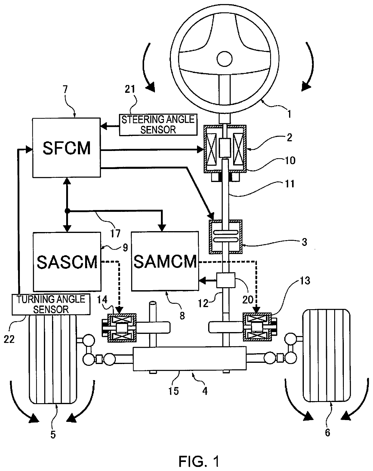
[0023]FIG. 1 illustrates a steering-by-wire system to which the method and device for controlling steering of a vehicle of the first embodiment are applied. The overall system will be described below with reference to FIG. 1.

[0024]In terms of a mechanical system, the steering-by-wire system comprises a steering wheel 1, a steering force actuator 2, a steer...


PUM


Abstract

A vehicle steering control method in which steering wheel vibrations are suppressed when a clutch is engaged while turning to suppress a sense of discomfort imparted to the driver. In this method, when transitioning from a steer-by-wire mode under an autonomous driving mode in which a steering clutch, through which a steering wheel and left and right front wheels are mechanically disconnected and connected, is disengaged, to an EPS control mode under a manual driving mode in which the steering clutch is engaged and an assist torque that corresponds to a detected torque from a torque sensor is imparted to the left and right front wheels, the steering clutch is engaged, and the assist torque is limited to a value that corresponds to the detected torque from the torque sensor from when the steering clutch is engaged until a prescribed limitation period has passed.

Description

CROSS-REFERENCE TO RELATED APPLICATIONS[0001]This application is a U.S. national stage application of International Application No. PCT / JP2018 / 008437, filed on Mar. 6, 2018.BACKGROUNDTechnical Field[0002]The present disclosure relates to a vehicle steering control method and a vehicle steering control device.Background Information[0003]A device for controlling steering of a vehicle using what is called a steer-by-wire system is hitherto known (e.g., see Japanese Laid-Open Patent Application No. 2015-44479). In this prior art, under normal circumstances, a clutch is placed in a disengaged state in which a steering wheel and turnable wheels are mechanically isolated from one another, and the turnable wheels are turned using drive force from a turning actuator. However, under circumstances in which an abnormal event has occurred, the clutch is placed in an engaged state in which the steering wheel and the turnable wheels are mechanically coupled to one another, and the turnable wheels ...

Claims


Application Information

Patent Timeline
IPC IPC(8): B62D5/04B62D5/00
CPCB62D5/043B62D5/006B62D5/0463B62D5/0481B62D15/025B62D5/003B62D1/286B62D5/0457
Inventor KAMEMURA, TAKAFUMI
Owner NISSAN MOTOR CO LTD
Why Eureka
Try Eureka