Motor control for powered closure with Anti-pinch

a technology of motor control and power striker, which is applied in the direction of wing accessories, electrical locking circuits, lock applications, etc., can solve the problems of lack of an override system lack of any adjustment of the striker, and inability to open the door, etc., and achieve the effect of convenient shutting

Pending Publication Date: 2020-12-17
TRI MARK CORP
View PDF32 Cites 1 Cited by
  • Summary
  • Abstract
  • Description
  • Claims
  • Application Information

AI Technical Summary

Benefits of technology

[0016]A motorized moveable striker is mounted to a door post where a fixed striker would normally be mounted and provides prescribed linear movement of the striker. This movement provides extension of the door edge more specifically near the latch when the latch is engaged, such that the door can be easily shut on the striker with minimal effort and then drawn to a normally closed position where the door is compressed into the door seal fully sealing the door. In the current design, the striker moves approximately 1″ between an extended position to a retracted position, but it is recognized that this dimension could be reduced or extended depending on the final application, design of the door and seals. Once the door is fully latched onto the extended striker, a switch in the rotary latch tells the control system that the latch is in place, and then the striker control system detects that the latch is in place and begins to move the striker to its retracted and sealed position. As this happens the door is drawn into its normally closed position which engages the seal with the frame and the door becomes sealed as it moves to its normally closed position. Upon releasing the latch through a releasing mechanism, the switch in the rotary latch tells the controller that the latch has been removed from the striker, and then the striker control system detects that the latch has been removed from the striker and the control extends the striker to approximately 1″ outward of the retracted position. This prescribed outboard movement moves the striker into extended position which allows for the next latching event. This motorized moveable striker system will lessen the events where a door is only partially engaged because it offers a closing event that is not impeded by door seal or air compression. This is accomplished as the door engages the door seal as the striker moves to the retracted closed position after the latch has been engaged with the striker.

Problems solved by technology

One problem with prior art cinching latches is the lack of an override system to open the door in the event that there is a power failure to the motor.
If the door is closed and power to the motor is cut off, for example if the vehicle battery is dead, the door cannot be opened.
Such a lockout condition is undesirable if ingress or egress is needed, potentially causing an unsafe condition.
Another problem with prior art powered strikers is the lack of any adjustment of the striker.
Therefore, any variances in manufacturing due to acceptable tolerances reduces or minimizes the effectiveness of the powered striker.
Another deficiency of the prior art powered strikers is the relatively short travel that is commercially available, typically 6-8 millimeters (0.24-0.31 inch).
This distance is not enough to allow large doors to engage the striker without starting to compress the door seals.
In tractors and cabs of heavy duty equipment, the size of the doors, the door seals, and compression of air inside the cabs are making it difficult to close the door without excessive force and speed.
Similarly, the large door size necessitates larger seals with more surface area, which also increases the force required to close and seal the door in the door frame.

Method used


Image

  • Motor control for powered closure with Anti-pinch
  • Motor control for powered closure with Anti-pinch
  • Motor control for powered closure with Anti-pinch

Examples


Embodiment Construction

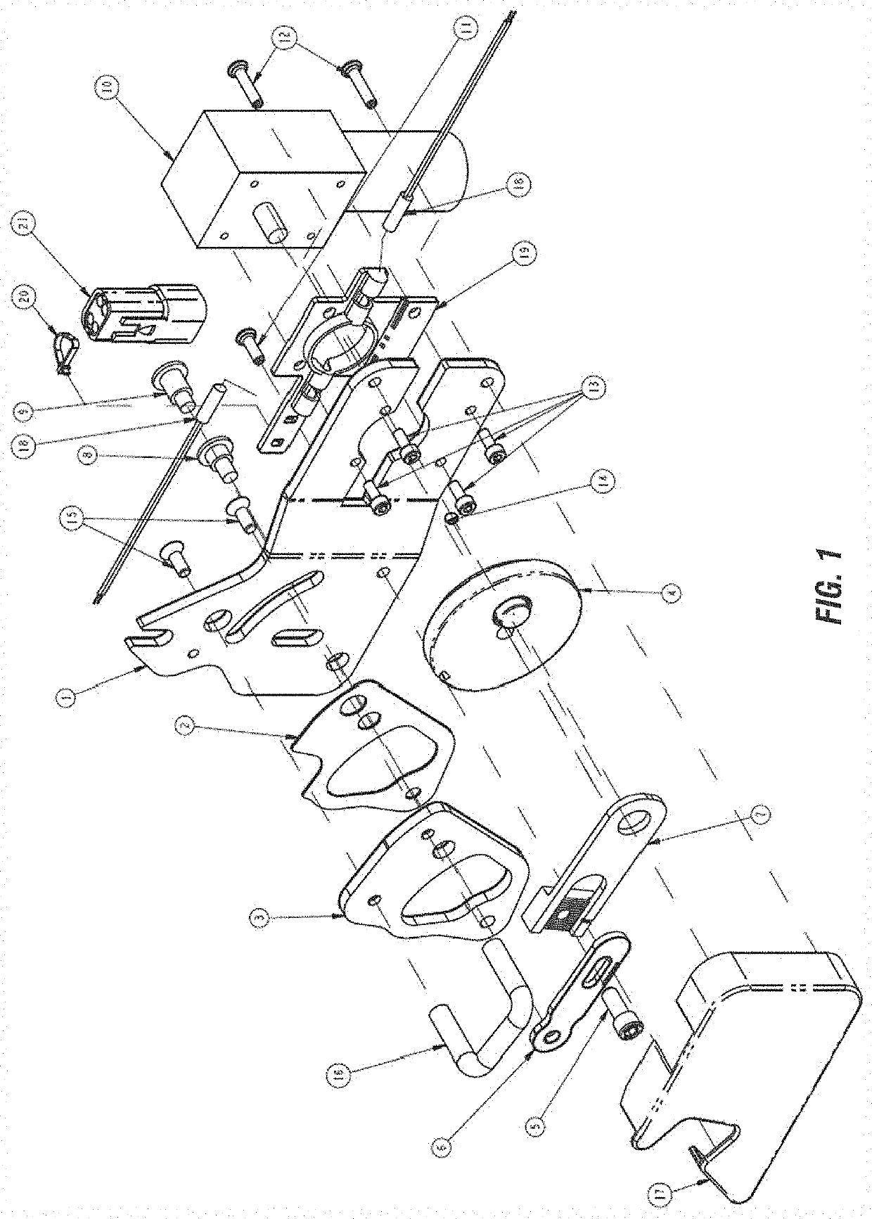
[0056]The following part list describes the components and their functions, using reference numerals corresponding to the drawings.

1. Mount plate—provides mounting surfaces for all cinching mechanism parts and provides mounting and mounting adjustment details for mounting to the vehicle.

2. Glide—isolates the moveable pivot plate 3 from the mounting plate 1 to reduce friction and wear.

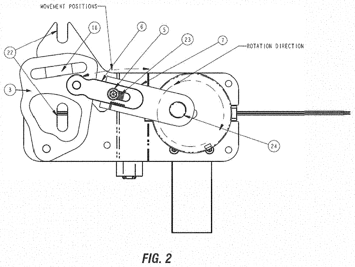
3. Pivot Plate—provides a base with a mounting surface for moveable apparatus, also has a pivot rivet mounting hole 67, and a pivot plate drive hole 58.

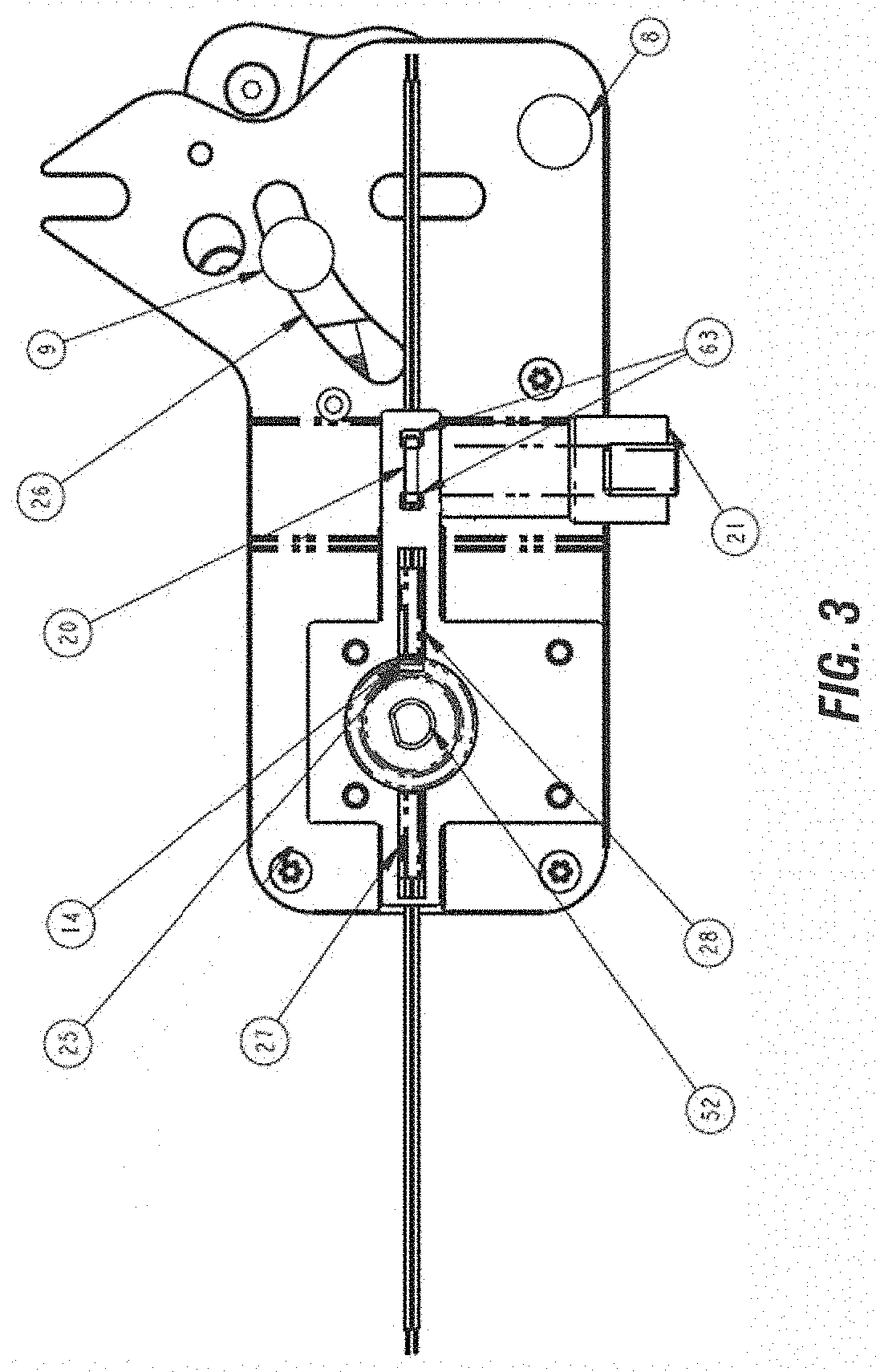
4. Torque Wheel—houses a magnet 14 for positional sensing, provides a drive feature for the motor interface, and a drive feature for a link that connects the torque wheel to the pivot plate 3.

5. Link Adjustment Screw—provides positive retention between the adjustable link components.

6. Driven Link—attaches to the pivot plate 3 via the drive rivet 9 and interfaces with the drive link 7 through the link adjustment screw 5.

7. Drive Link—attaches to the torq...


PUM


Abstract

A controller system is provided for a motorized moveable striker assembly on a vehicle door or window. The assembly includes a striker on the door post which is moveable by an electric motor between extended and retracted positions. A latch on the door releasably engages the striker. Switches in the latch sends signals to the controller to actuate the motor. After the latch is engaged, the controller retracts the striker from the extended position to fully close the door. When the latch is disengaged from the striker, the latch switch sends a signal to controller to actuate the motor so as to extend the striker from the retracted position to the extended position as to prepare for the next door closing. Anti-pinching control and temperature compensation is also provided.

Description

FIELD OF INVENTION[0001]The present invention relates to a motor control for a power striker for hinged personnel doors and windows for vehicular applications. The invention can be applied to any enclosable portal of which doors and windows are included. The terms “door” or “window” operate as an all-inclusive term when found in this specification.BACKGROUND OF THE INVENTION[0002]Generally power door latch systems are known within the automotive and other vehicular field and are used to overcome the high force requirements to move doors and trunks into the fully closed position. Applications range from personnel doors, trunk lids, lift gates and sliding doors on mini-vans. There generally are two types of powered door closure devices; a cinching latch where a rotary latch with a claw or rotor is driven to rotate by a motor and cinch the striker approximately 6-8 millimeters and a powered striker where the striker is motorized to engage with the rotary latch and pull the door into th...

Claims


Application Information

Patent Timeline
Patent Type & Authority Applications(United States)
IPC IPC(8): E05B81/64E05B81/14E05B81/44E05B81/06E05B83/36
CPCE05B81/14E05B83/36E05B81/64E05B81/06E05Y2900/531E05Y2400/552E05B81/44E05B81/21E05B81/22E05B81/66E05B81/90E05B15/024E05B81/62E05B81/74E05B85/04
Inventor MARSHALL, GLEN A.
Owner TRI MARK CORP
Why Eureka
Try Eureka