Cast In-Ground Lighting Assembly

a technology of lighting assembly and cast in ground, which is applied in the direction of lighting and heating apparatus, lighting support devices, and ways, etc., can solve the problems of limited maintenance, achieve the effect of reducing the amount of parts and materials required, facilitating a simple installation of a drive, and cost-effective

Active Publication Date: 2020-12-17
ST IVES LAURENCE ROBERT
View PDF0 Cites 4 Cited by
  • Summary
  • Abstract
  • Description
  • Claims
  • Application Information

AI Technical Summary

Benefits of technology

[0004]The present invention is directed to a cast concrete durable light fixture design that will reduce the parts and materials required and facilitate a simpler installation of a drive over in-grade or in-ground lighting fixture. The cast concrete design enables curves and shapes to be manufactured as easily as straight or linear configurations. Casting fixtures as precast interlocking sections from concrete, polymer concrete mixtures or other non-corrosive structural materials, which will withstand heavy drive over traffic, solves the environmental problems associated with present metal body in-ground lighting system applications in a cost-effective configuration.
[0005]The present invention optimizes the advantages of light emitting diode (LED) lights for in-ground lighting architectural products. LED versions can provide colored or color changing effects. The miniature size of LEDs enables the creation of narrow linear images. The long life of the LEDs are particularly suitable for the in-ground applications due to their long useful lifetime as compared to other types of lights, and the LED's require limited maintenance. Recent developments of long flexible LED strips with miniaturized electronics using standard line voltages, which can be run continuously in lengths as long as 300 feet, enable new fixture designs to be created which are free-form as well as straight linear lines. In addition, because of the LED low energy requirements, they can be used economically due to their energy efficiency.

Problems solved by technology

The long life of the LEDs are particularly suitable for the in-ground applications due to their long useful lifetime as compared to other types of lights, and the LED's require limited maintenance.

Method used


Image

  • Cast In-Ground Lighting Assembly
  • Cast In-Ground Lighting Assembly
  • Cast In-Ground Lighting Assembly

Examples


first embodiment

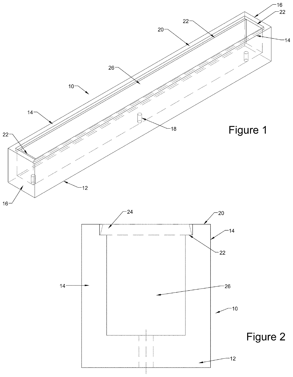
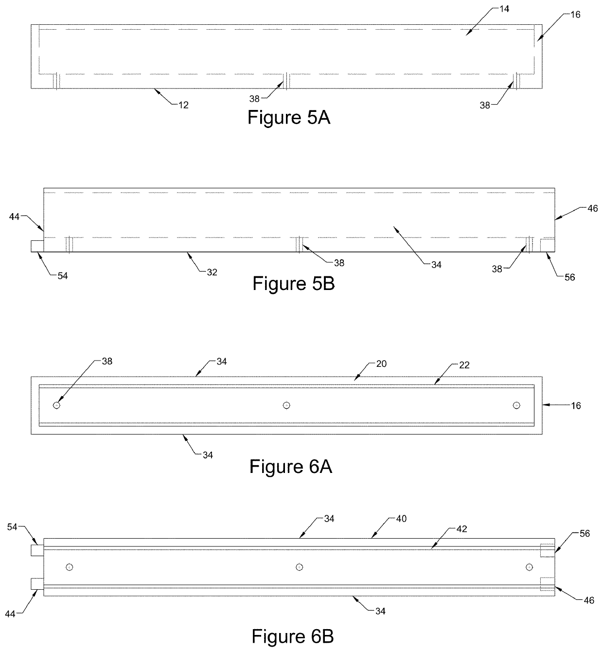
[0022]FIG. 1 is a perspective view and FIG. 2 is an end view of the cast concrete body 10 of an in-ground lighting assembly of the present invention. The cast concrete body 10 includes a base 12 and sidewalls 14 extending upward from the outer edges of the base 12. The cast concrete body 10 may also include endcaps 16. The cast concrete body 10 may be formed in the shape of a square or rectangle with three-quarters of an inch to twelve inch wide base and three-quarters of an inch to six inch tall sides, and up four or even eight feet in length. The base 12 may include one or more drain holes 18 that can also be used to allow wiring access to the interior of the cast concrete body 10. The top edges 20 of the sidewalls 14 as well as the endcaps 16 preferably include a shoulder 22 formed to support the edges of a lens 24, as illustrated in the end view of FIGS. 1 and 2. The base 12 and sidewalls 14 form an open channel 26 for placement of electrical elements including lights, preferabl...

second embodiment

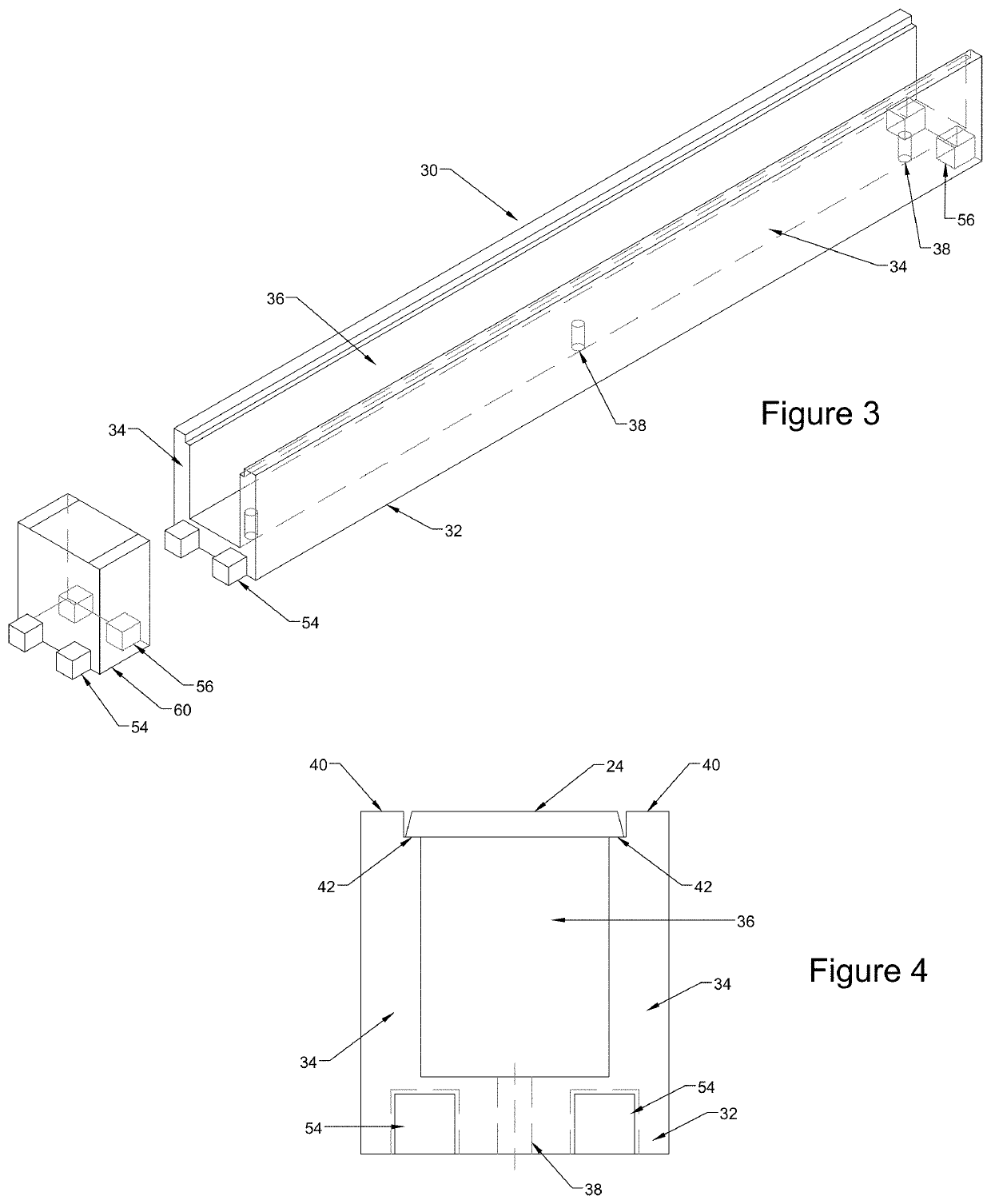
[0023]FIG. 3 is a perspective view and FIG. 4 is an end view of the cast concrete body 30 of an in-ground lighting assembly of the present invention. The cast concrete body 30 includes a base 32 and sidewalls 34 extending upward from the outer edges of the base 32. The base 32 may include one or more drain holes 38. As depicted in FIGS. 3 and 4, the cast concrete body 30 forms an open-ended channel 36 for receiving the LED lighting arrays. The top surfaces 40 of the sidewalls 34 each include shoulders 42 to support a lens 24. The respective ends 44 and 46 of the cast concrete body 30 preferably include interlocking male 54 and female 56 connector features. The connector features are depicted as having square shapes, although it should be understood that the connector features could have other cross-sectional shapes including round, oval, triangles and rectangular shapes. The connector features allow the easy assembly of two or more of the cast concrete bodies 30 end to end allowing ...

third embodiment

[0026]FIG. 7 is a top view of the cast concrete body 70 of an in-ground lighting assembly of the present invention having a curved design. The cast concrete body 70 has a base (hidden in FIG. 7) and sidewalls 74 defining a channel 76 similar to the construction of the above described embodiments. However, the cast concrete body 70 is formed to a curved or arcuate shape as opposed to the linear designs of FIGS. 1 and 3. FIG. 7 thus illustrates the flexibility of the present invention in allowing a non-linear cast concrete body 70 to be formed and joined end-to-end to allow free form designs. The multiple cast concrete bodies 70 depicted in FIG. 7 include respective ends 80 and 82 preferably include interlocking male 84 and female 86 connector features, similar to those described above with respect to FIGS. 3 and 4. FIG. 7 depicts two cast concrete bodies70 spaced apart in preparation for assembly in the top half of the figure, and two cast concrete bodies70 joined together in the bot...


PUM


Abstract

A cast concrete durable light fixture design and assembly that will allow in-ground lighting features for roadways, pathways and architectural features providing a simple installation for a drive over in-grade or in-ground lighting fixture. The cast concrete design enables curves and shapes to be manufactured as easily as straight or linear configurations.

Description

BACKGROUND AND PRIOR ART[0001]In-ground or below grade lighting systems provide a number of desirable benefits and enhancements to building designs and architectural features. In-ground linear lighting can be used to create unobtrusive, directional or decorative illumination in pedestrian or vehicular traffic areas, which will not obstruct traffic. Placing the lighting features in-ground has an added benefit of making the lighting vandal resistant. In-ground lighting can be used to delineate pathways and access points or to direct illumination on architectural structures and facades. However, in-ground lighting systems are exposed to a number of environmental factors, including water, salt water, corrosive materials and chemicals, requiring special design considerations. Examples of in-ground lighting systems are disclosed in U.S. Pat. Nos. 7,478,916; 9,638,381; 9,784,440 and 10,082,260.[0002]In-ground light fixtures intended to be used in roadways, driveways and entrances, which ma...

Claims


Application Information

Patent Timeline
Patent Type & Authority Applications(United States)
IPC IPC(8): F21S8/02F21V15/01F21V17/10F21V19/00
CPCF21Y2115/10F21S8/022F21V15/01F21W2131/10F21V17/107F21V19/001F21W2131/103F21S4/28F21S2/00F21V21/005E01F9/582
Inventor ST.IVES, LAURENCE ROBERT
Owner ST IVES LAURENCE ROBERT
Why Eureka
Try Eureka