Sensor-based shape identification

Pending Publication Date: 2020-12-24
KONINKLJIJKE PHILIPS NV
View PDF3 Cites 1 Cited by
  • Summary
  • Abstract
  • Description
  • Claims
  • Application Information

AI Technical Summary

Problems solved by technology

Additionally, the illustrations are merely re

Method used


Image

  • Sensor-based shape identification
  • Sensor-based shape identification
  • Sensor-based shape identification

Examples


Example

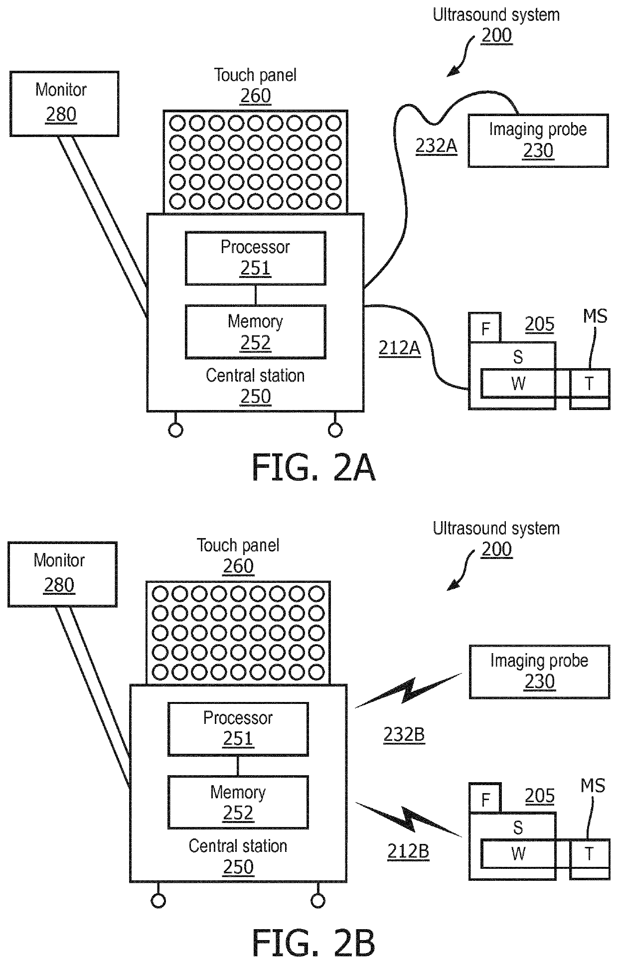
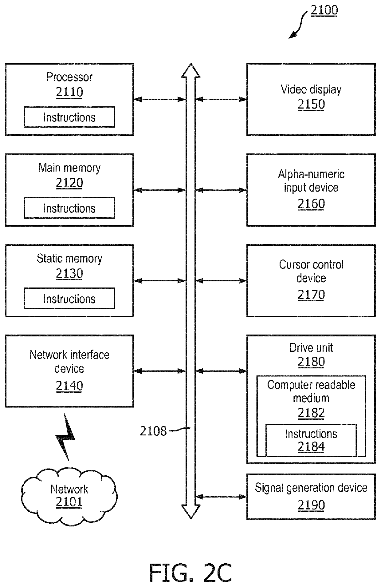
[0019]In the following detailed description, for purposes of explanation and not limitation, representative embodiments disclosing specific details are set forth in order to provide a thorough understanding of an embodiment according to the present teachings. Descriptions of known systems, devices, materials, methods of operation and methods of manufacture may be omitted so as to avoid obscuring the description of the representative embodiments. Nonetheless, systems, devices, materials and methods that are within the purview of one of ordinary skill in the art are within the scope of the present teachings and may be used in accordance with the representative embodiments. It is to be understood that the terminology used herein is for purposes of describing particular embodiments only, and is not intended to be limiting. The defined terms are in addition to the technical and scientific meanings of the defined terms as commonly understood and accepted in the technical field of the pres...


PUM


Abstract

A controller for determining shape of an interventional device includes a memory that stores instructions, and a processor that executes the instructions. When executed by the processor, the instructions cause the controller to execute a process that includes controlling an imaging probe to emit at least one tracking beam to an interventional medical device over a period of time comprising multiple different points of time. The process also includes determining a shape of the interventional medical device, based on a response to the tracking beams received over the period of time from a first sensor that moves along the interventional medical device during the period of time relative to a fixed location on the interventional medical device for the period of time.

Description

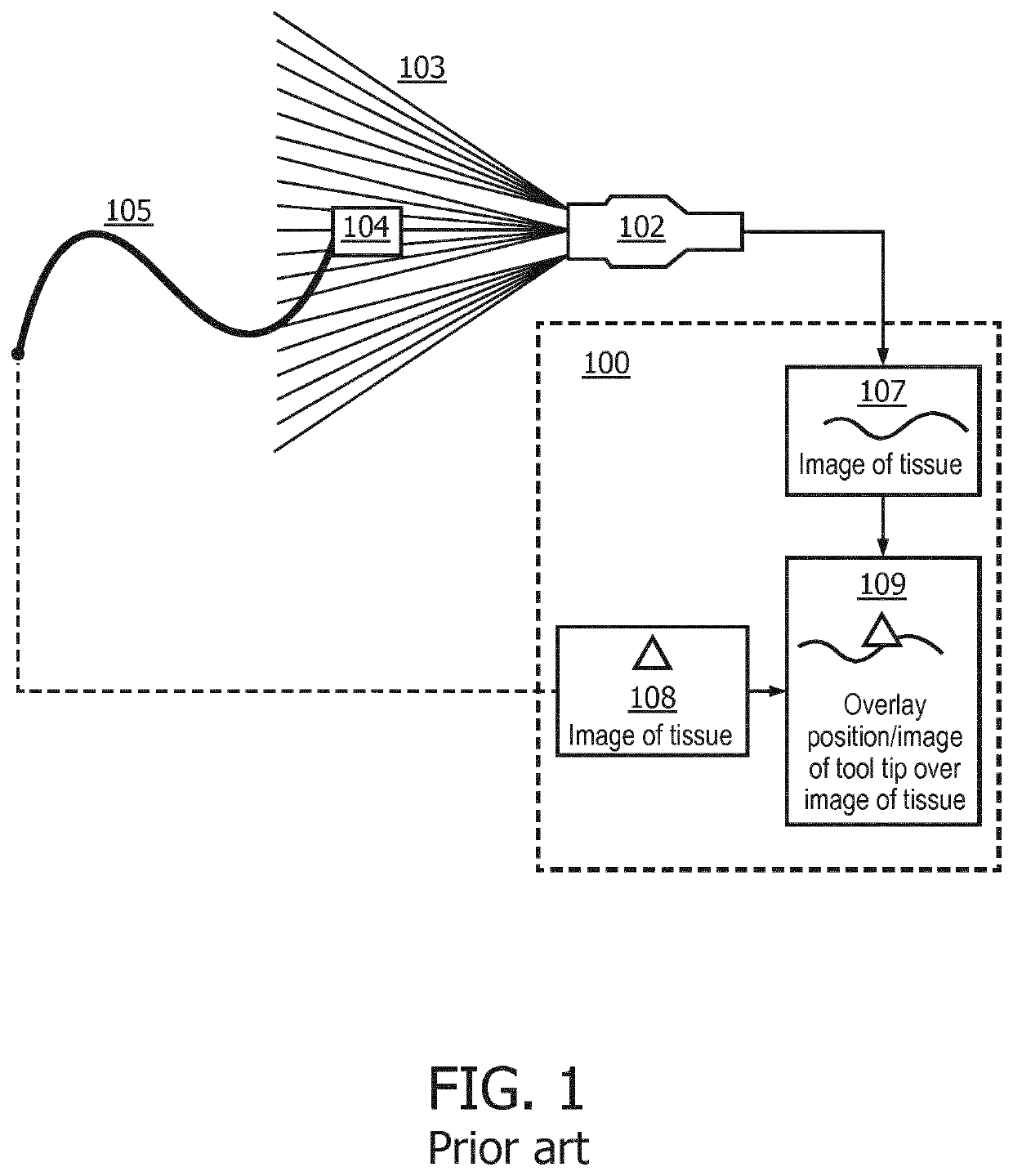
BACKGROUND[0001]InSitu technology estimates position of a passive ultrasound sensor in the field of view of a known diagnostic B-mode ultrasound image by analyzing the signal received by the passive ultrasound sensor as the beams of the ultrasound imaging probe sweep the insonified field. Time-of-flight measurements provide the axial / radial distance of the passive ultrasound sensor from the imaging array, while amplitude measurements and knowledge of the beam firing sequence provide the lateral / angular position of the passive ultrasound sensor.[0002]FIG. 1 illustrates a known system for tracking an interventional medical device using a passive ultrasound sensor. In FIG. 1, an ultrasound probe 102 emits an imaging beam 103 that sweeps across a passive ultrasound sensor 104 on a tool tip of an interventional medical device 105. An image of tissue 107 is fed back by the ultrasound probe 102. A location of the passive ultrasound sensor 104 on the tool tip of the interventional medical d...

Claims


Application Information

Patent Timeline
IPC IPC(8): A61B8/08G01S15/89A61B8/00
CPCA61B8/0841G01S15/8934A61B8/54A61B8/4254A61B8/4263A61B2034/2061A61B2034/2063A61B2090/062A61B2090/3925A61B5/064A61B34/20A61B90/90A61B2090/378A61B2090/364A61B2090/3937A61B2090/0811A61B2090/376A61B2090/374G01S5/18G01S2205/01
Inventor CHEN, ALVINERKAMP, RAMON QUIDOBHARAT, SHYAMVAIDYA, KUNALTORJESEN, ALYSSAFLEXMAN, MOLLY LARAJAIN, AMEET KUMAR
Owner KONINKLJIJKE PHILIPS NV
Why Eureka
Try Eureka