
Modular point-of-care devices, systems, and uses thereof

a point-of-care device and module technology, applied in the field of modules, can solve the problem of unmet needs for alternative designs of poc devices

Active Publication Date: 2009-04-02
LABRADOR DIAGNOSTICS LLC
View PDF16 Cites 315 Cited by
  • Summary
  • Abstract
  • Description
  • Claims
  • Application Information

AI Technical Summary

Benefits of technology

[0165]One advantage of some of the features described herein is that information can be transmitted from the external device back to not only the reader assembly, but to other parties or other external devices, for example without limitation, a PDA or cell phone. Such communication can be accomplished via a wireless network as disclosed herein. In some embodiments a calculated analyte concentration or other patient information can be sent to, for example but not limited to, medical personnel or the patient.

Problems solved by technology

Thus, there remains an unmet need for alternative designs of POC devices.

Method used


Image

  • Modular point-of-care devices, systems, and uses thereof
  • Modular point-of-care devices, systems, and uses thereof
  • Modular point-of-care devices, systems, and uses thereof

Examples


example 1

[0287]In this example, a device, method, and system of the invention are used to perform an assay for human VEGFR2. The example demonstrates a type of assay that can be performed at the point of care. The capture surface of an assay unit can be coated onto the assay unit according to the assay, this example a VEGFR2 assay. The inner surface of the assay unit (made from injection molded polystyrene similar to example in FIG. 3A) was exposed to a succession of coating reagents by aspiration and pneumatic ejection. Twenty microliters of each coating reagents were drawn into assay units and incubated at room temperature for 10 minutes. The coating reagents used in this example are, as used in succession, Neutravidin (20 ug / mL) in Carbonate-Bicarbonate buffer (pH 9), biotinylated “capture antibody” (a monoclonal antibody directed to VEGFR2 at 20 ug / mL) in Tris buffered saline, (pH 8), and a “fixative” reagent containing 3% bovine serum albumin in Tris-buffered saline. After the successio...

example 2

[0290]An assay for human P1GF was performed using the assay units and reagent units of the invention and read in a commercial instrument. In parallel an assay using the same reagents was done in prototype disposable cartridges (as described below) in a prototype reader. Analyte concentrations were 0, 4, 80 and 400 pg / mL respectively. The measurements illustrated in FIG. 13 were used to calibrate an assay unit and reagent unit necessary for conducting an assay for human P1GF.

example 3

[0291]Magnetizable beads are 1.3 um diameter BioMag magnetic particles from Bangs Laboratories. Beads are coated (by the manufacturer) with anti-Rabbit IgG. Beads are dispersed at 14 mg / mL in tris-buffered sucrose (or, alternatively, tris buffered saline) containing 3% bovine serum albumin and rabbit anti-human red blood cell IgG, from CedarLane at >=1.15 mg / mL. Aliquots (10 uL of this dispersion were dispensed into conical tubes and lyophilized (frozen in liquid N2 and lyophilized for approximately 24 hrs. at −70 C) prior to insertion into a slot in the cartridge housing. The rabbit antibody binds both to the red cells and to the anti-rabbit IgG-coated beads and forms a co-agglutinate of beads and red cells.

[0292]The lyophilized magnetizable bead pellet was re-suspended by adding 20 uL of whole blood then aspirating and dispensing at least 8 times (approximately 1.5 min) into a conical tube.

[0293]Blood was separated by placing the tip (in a vertical orientation) in a strong, horizo...


PUM

PropertyMeasurementUnit
Fractionaaaaaaaaaa
Volumeaaaaaaaaaa
Volumeaaaaaaaaaa

Abstract

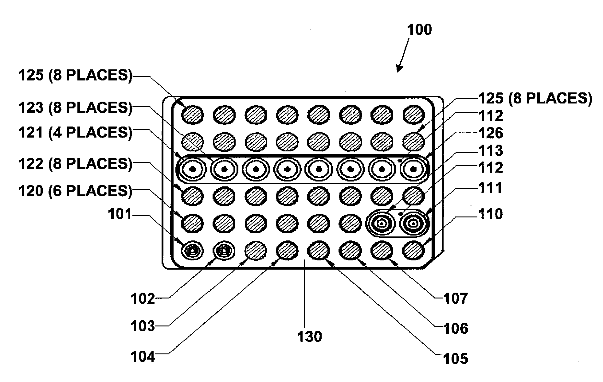
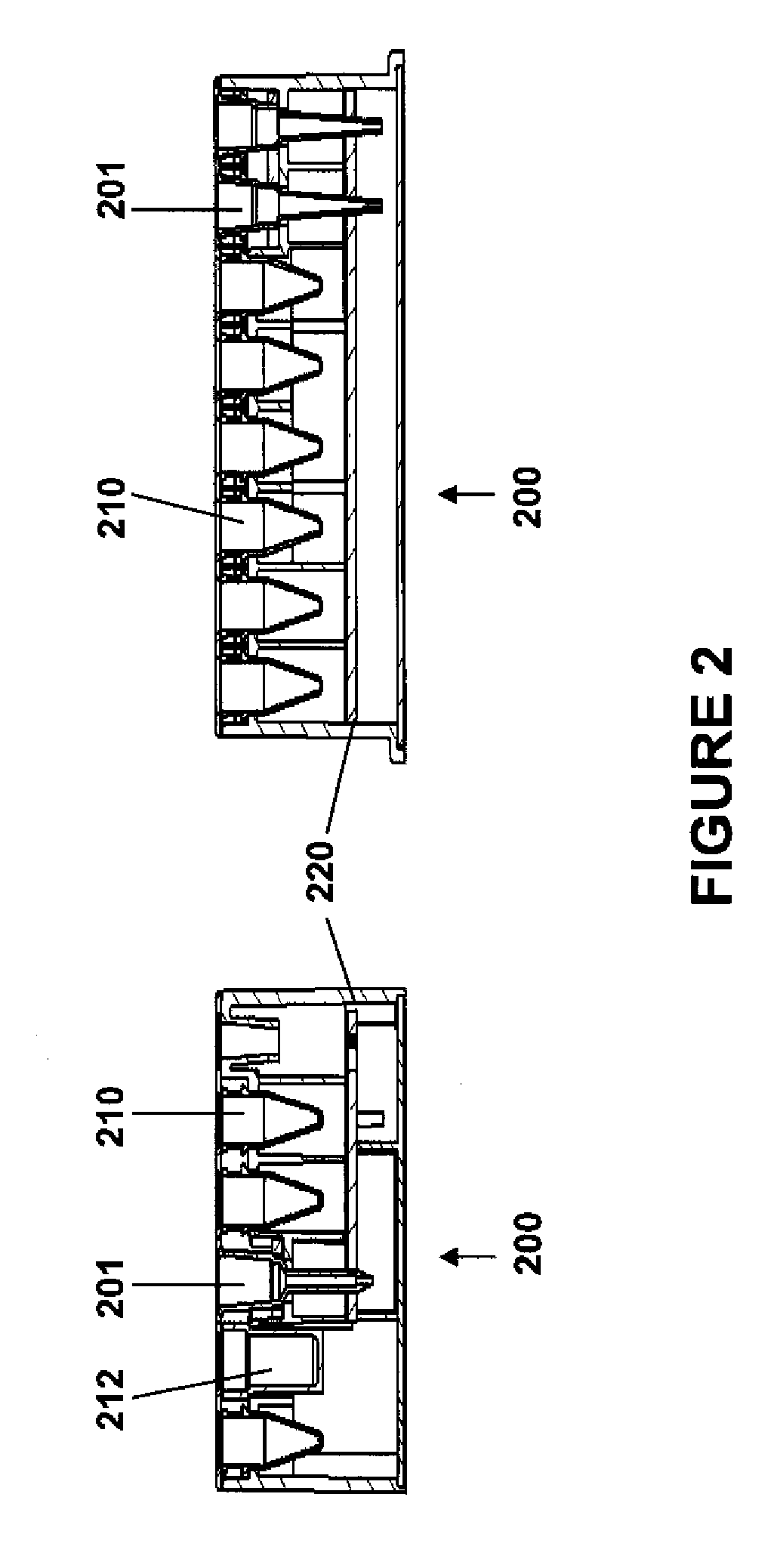
The present invention provides devices and systems for use at the point of care. The methods devices of the invention are directed toward automatic detection of analytes in a bodily fluid. The components of the device are modular to allow for flexibility and robustness of use with the disclosed methods for a variety of medical applications.

Description

CROSS-REFERENCE[0001]This application claims the benefit of U.S. Provisional Application No. 60 / 997,460, filed Oct. 2, 2007, which application is incorporated herein by reference in its entirety.BACKGROUND OF THE INVENTION[0002]The discovery of a vast number of disease biomarkers and the establishment of miniaturized medical systems have opened up new avenues for the prediction, diagnosis and monitoring of treatment of diseases in a point-of-care setting. Point-of-care systems can rapidly deliver test results to medical personnel, other medical professionals and patients. Early diagnosis of a disease or disease progression can allow medical personnel to begin or modify therapy in a timely manner.[0003]Multiplexed biomarker measurement can provide additional knowledge of the condition of a patient. For example, when monitoring the effects of a drug, three or more biomarkers can be measured in parallel. Typically, microtiter plates and other similar apparatuses have been used to perfo...

Claims


Application Information

Patent Timeline
IPC IPC(8): C40B30/04C40B60/12
CPCB01J19/0046Y10T436/25375B01J2219/00292B01J2219/00315B01J2219/00369B01J2219/00371B01J2219/00385B01J2219/00466B01J2219/00495B01J2219/005B01J2219/00693B01J2219/00702B01L3/021B01L3/0262B01L3/5025B01L3/527B01L2200/04B01L2200/0689B01L2200/141B01L2200/148B01L2300/0654B01L2300/0829B01L2300/1805B01L2400/043G01N35/028G01N2035/0097G01N33/54386G01N1/38G01N33/5302G01N33/56966G01N2333/71Y10T29/49826B01J2219/00283B01L9/543G16H10/40G01N2333/4737A61B10/0038A61B10/0045A61B10/0051A61B10/0058A61B10/007A61B10/02A61B2010/0074A61B2010/0077G01N33/48G01N33/5091G01N33/53G01N35/08C12M1/266C12M1/02G01N37/00G01N33/50G01N35/02G01N35/10B01L7/5255G01N2333/475G01N33/54326A61B5/150755A61B5/151G01N33/5304G01N2333/9129G01N35/1065B01L7/52G01N33/6803G01N2800/60G01N33/94G01N2333/91205G01N33/54366G01N35/00732G01N35/00871G01N2035/00237G01N2035/00851G01N2035/1032G01N2800/26A61B5/15G01N35/1074G01N2035/00881G01N2035/1034G01N2035/1048G01N33/57484G01N2333/912
Inventor BURD, TAMMYGIBBONS, IANHOLMES, ELIZABETH A.FRENZEL, GARYNUGENT, ANTHONY JOSEPH
Owner LABRADOR DIAGNOSTICS LLC
Learn More