Internal magnetic resistance system for use with fitness device

US20200398097A1Active Publication Date: 2020-12-24CHANG YOW TECH INT

Image

  • Internal magnetic resistance system for use with fitness device
  • Internal magnetic resistance system for use with fitness device
  • Internal magnetic resistance system for use with fitness device

Examples


Embodiment Construction

[0023]Direction-related terms used herein, including the embodiments and the claims, must be interpreted according to the accompanying drawings. Identical reference numerals used herein, including the embodiments and the accompanying drawings, denote identical or similar components or structural features thereof.

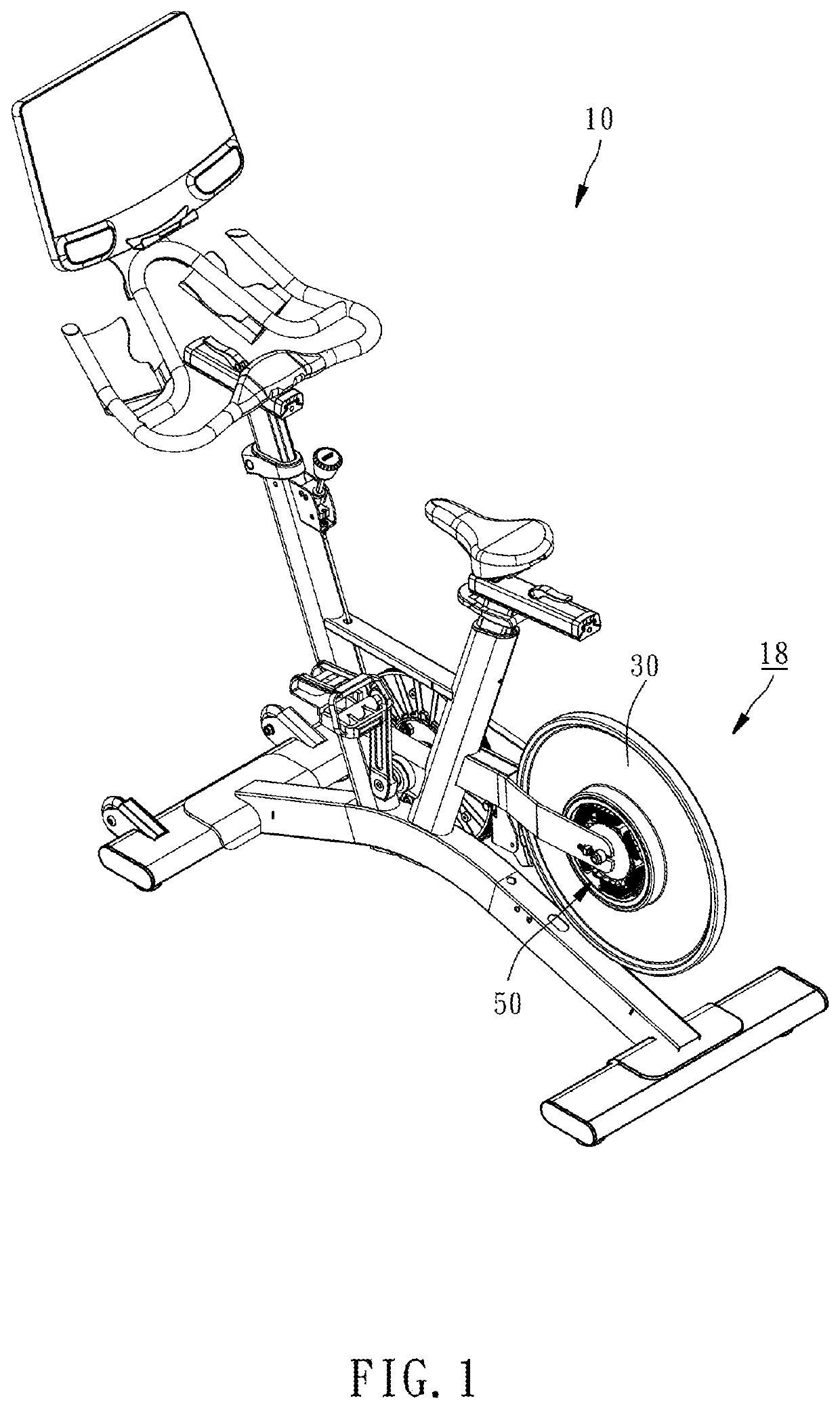
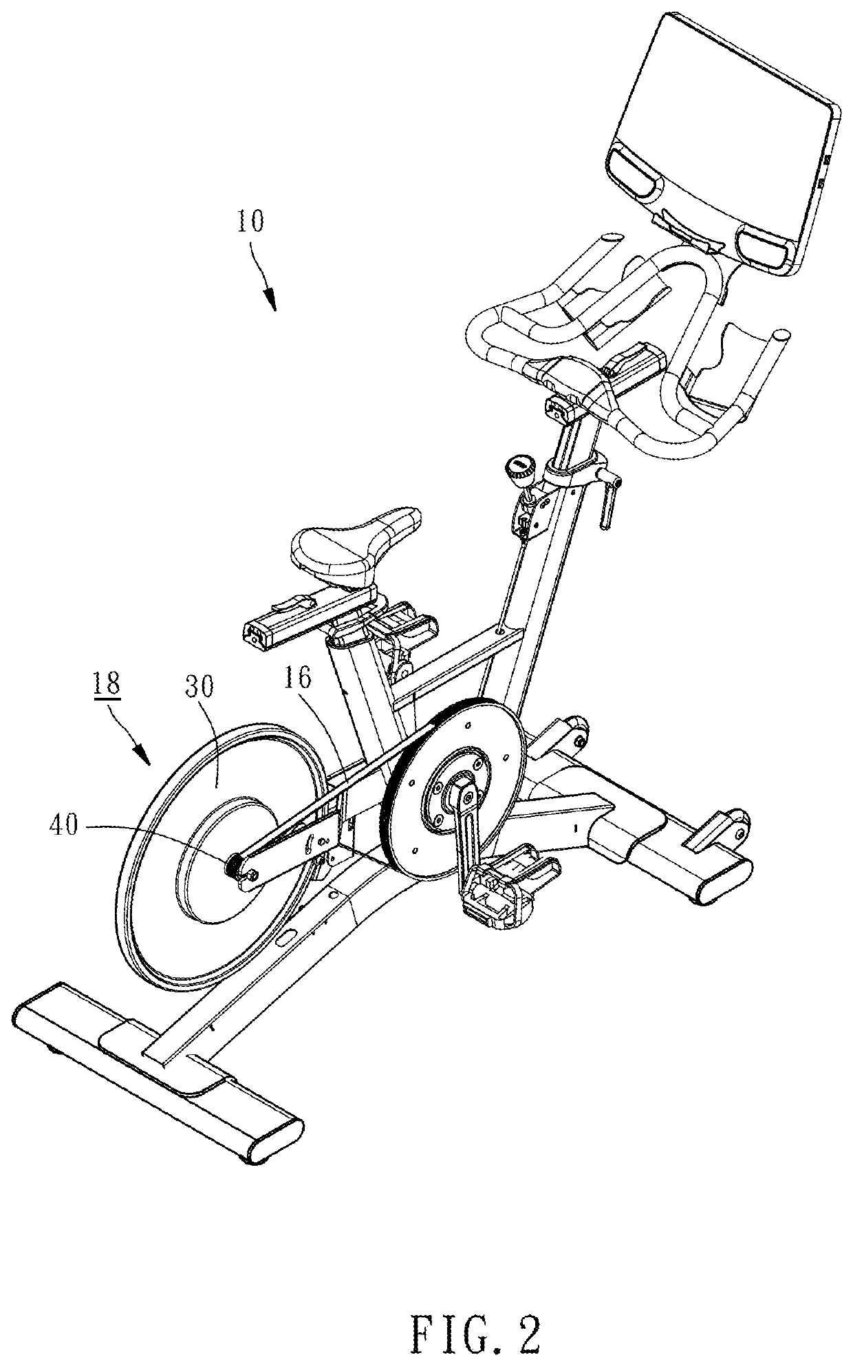
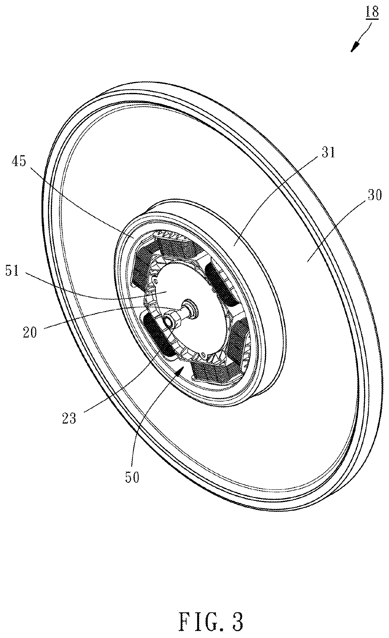
[0024]Referring to FIG. 1 and FIG. 2, FIG. 1 shows an upright body-building bike for use with a fitness device 10. Referring to FIG. 3 through FIG. 5, an internal magnetic resistance system 18 of the present disclosure comprises an axle 20, an inertia wheel 30, a transmission wheel 40, a magnetic permeable ring 45 and an electromagnet 50.

[0025]The left and right ends of the axle 20 each have a thread segment 21. A first keyway 22 is disposed at the axle 20 and located centrally but slightly toward the left.

[0026]The inertia wheel 30 is made of cast iron. The left lateral surface of the inertia wheel 30 has a protruding ring portion 31 and a first axial portion 32 disposed in...


PUM


Abstract

An internal magnetic resistance system for use with a fitness device includes an axle, inertia wheel, transmission wheel, magnetic permeable ring and electromagnet. The inertia wheel is disposed at the axle and has a protruding ring portion. The transmission wheel connects to the inertia wheel and transfers an external force to the inertia wheel to cause the inertia wheel to rotate. An outer circumferential surface of the magnetic permeable ring is fixedly disposed on an inner circumferential surface of the protruding ring portion such that the magnetic permeable ring rotates together with the inertia wheel. The electromagnet is disposed in the protruding ring portion and surrounded by the magnetic permeable ring. The electromagnet has a support fixedly disposed at the axle and iron cores disposed at the support. Each said iron core is surrounded by a coil and separated from the magnetic permeable ring by a gap.

Description

BACKGROUND OF THE INVENTION1. Field of the Invention[0001]The present disclosure relates to fitness devices and, more particularly, to an internal magnetic resistance system for use with a fitness device.2. Description of the Related Art[0002]Conventional fitness devices (such as body-building bikes and elliptical trainers) are each equipped with a resistance system whereby users exert different degrees of resistance forces on a flywheel or any similar component, allowing the users to adjust the ease of operation according to the users' training needs and thus attain the benefits of fitness training.[0003]The resistance system is generally of three types: frictional, external magnetic and internal magnetic. The conventional frictional resistance system includes a brake rod and a friction patch. The friction path is made of cattle hide or wool quilt and adhered to the outer circumferential surface of the flywheel to generate resistance. The resistance strength of the conventional fri...

Claims


Application Information

Patent Timeline
24 Dec 2020
Publication
US20200398097A1
IPC
A63B21/005; H02K49/04; H02K1/18
CPC
A63B21/0052; H02K49/043; H02K1/187; A63B22/06; H02K7/14; H02K7/02; A63B22/0605; A63B21/225
Inventors
CHEN, CHAO-CHUAN