
Clarifier with Improved Energy Dissipating Inlet

a technology of energy dissipation inlet and clarifier, which is applied in the direction of sedimentation settling tank, sedimentation separation, separation process, etc., can solve the problems of difficult to push scum out of the clarification zone to be collected and removed by the clarifier's scum skimming system, and achieve the effect of simplifying the clarifier system and improving the performance efficiency of the clarifier

Pending Publication Date: 2020-12-24
OVIVO INC
View PDF4 Cites 0 Cited by
  • Summary
  • Abstract
  • Description
  • Claims
  • Application Information

AI Technical Summary

Benefits of technology

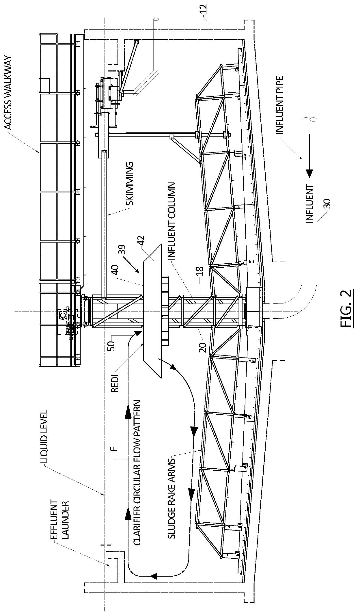
The invention is a new system for reducing sludge in tanks. It uses a reverse EDI (electrodes in reverse) that slows down the flow of sludge to promote settling of solids to the floor of the tank. This results in a reduction in material and installation costs compared to conventional systems. The reverse EDI design also eliminates a space where scum can accumulate, improving operational efficiency. Overall, the invention reduces costs and improves operational efficiency by promoting sludge settling and reducing space for scum.

Problems solved by technology

A problem of this conventional construction is cost, especially cost of material in the feedwell.
In addition, often the annular space between the EDI and feedwell vertical walls collects scum.
Even with feedwell scum ports and a scum spray system in the annular space it is difficult to push the scum out into the clarification zone to be collected and removed by the clarifier's scum skimming system.
In addition, submerged EDIs of the invention are effective in a clarifier which is also an equalizaion basin, with varying liquid level, which is generally not possible with conventional EDI / feedwell designs because they can never be fully submerged.

Method used


Image

  • Clarifier with Improved Energy Dissipating Inlet
  • Clarifier with Improved Energy Dissipating Inlet
  • Clarifier with Improved Energy Dissipating Inlet

Examples


Embodiment Construction

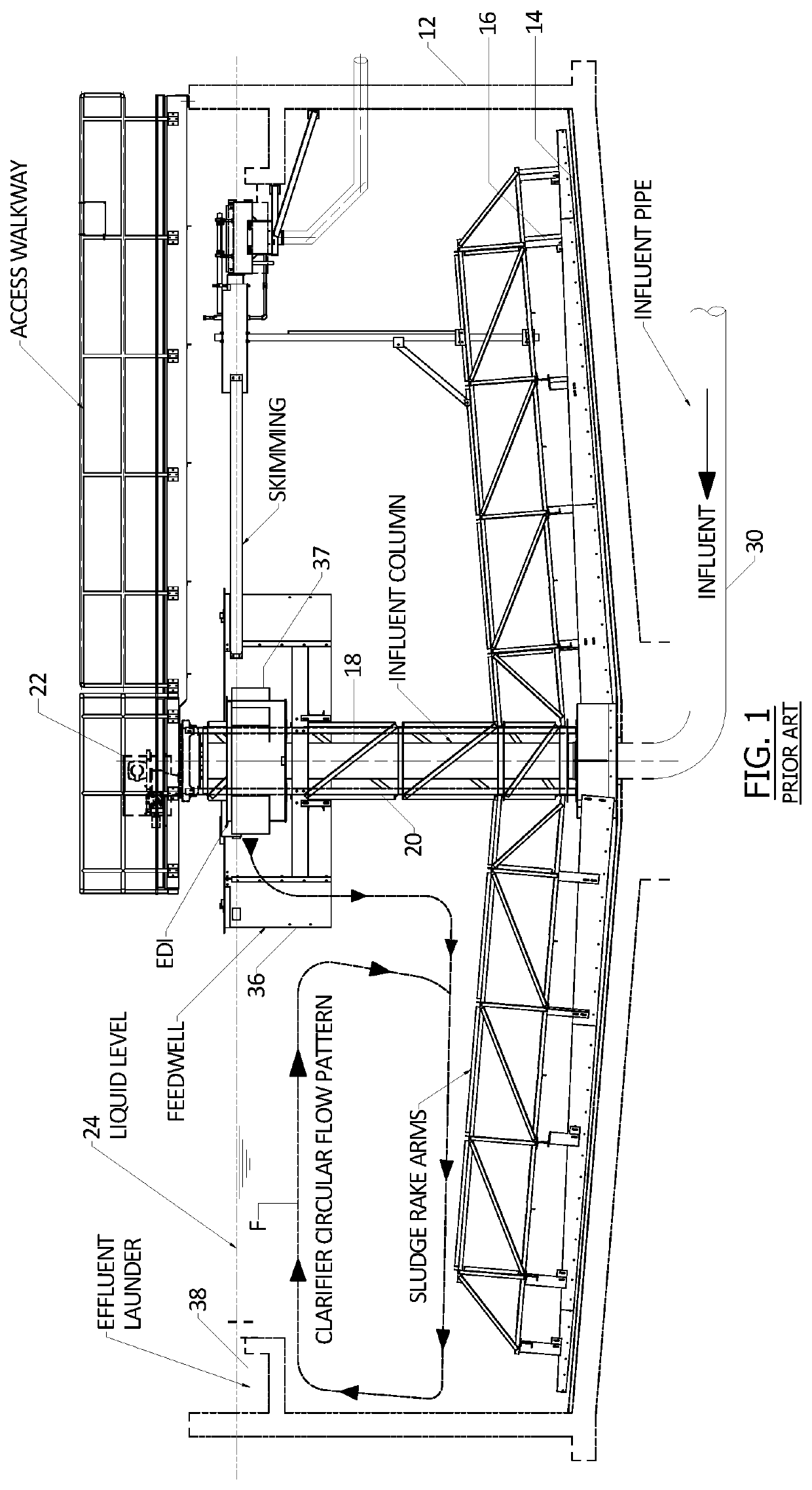
[0026]FIG. 1 shows a column supported center feed clarifier 10 in a conventional system, indicating prior art. The illustrated clarifier comprises a basin 12, typically concrete or steel, with a basin floor 14, sludge rake arms 16 and a central influent column 18. A rotating central cage is shown at 20, around the central column 18, at the top of which is equipment 22 that drives the rake arms via the cage 20. The liquid surface in the clarifier is indicated at 24.

[0027]Wastewater influent enters the clarifier via a pipe 30 beneath the floor, delivering the flow up through the central column 18, to be delivered into the clarifier through exit ports near an upper end of the column 18.

[0028]As in conventional clarifier design, the illustrated clarifier has a feedwell or stilling well 36, a vertically oriented annular band that extends slightly above the liquid surface 24 and down into the clarifier. As an example, in a conventional clarifier the feedwell or stilling well might have a ...


PUM

PropertyMeasurementUnit
velocityaaaaaaaaaa
velocityaaaaaaaaaa
velocityaaaaaaaaaa

Abstract

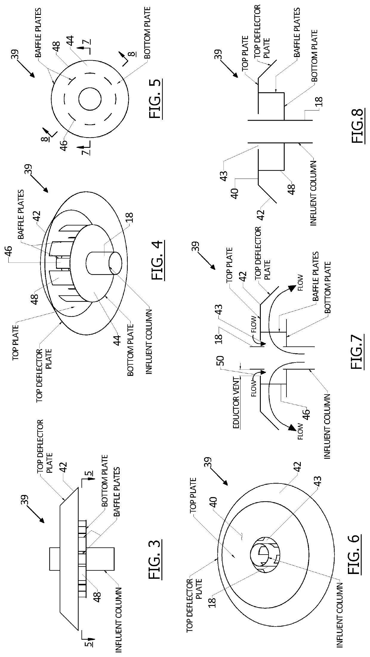
A clarifier of a wastewater treatment system is made more efficient and cost effective with an energy dissipating inlet (EDI) that removes the need for a conventional feedwell / EDI system. A central influent pipe has wastewater outlet ports under the liquid surface, the ports being surrounded by an efficient EDI surrounding the center pipe and extending outwardly therefrom. The EDI receives influent flow and directs the sludge outwardly and generally downwardly at reduced flow velocity. Series of baffles in the EDI help slow the flow velocity and disperse the sludge. In another embodiment a faucet-type EDI has discharge openings that disperse the sludge downwardly after it has flowed through sets of baffles above. Significant cost reductions in material and installation are realized by elimination of the conventional feedwell / EDI system.

Description

[0001]This application is a continuation-in-part of application Ser. No. 16 / 537,379, filed Aug. 9, 2019, now ______, which claimed benefit of provisional application No. 62 / 718,313, filed Aug. 13, 2018.BACKGROUND OF THE INVENTION[0002]This invention concerns a clarifier or sedimentation basin in a wastewater treatment system, and in particular is directed to an improved energy dissipating inlet (EDI) that eliminates the need for a feedwell in the clarifier.[0003]The typical flow for a standard column-supported clarifier enters the center pier / influent column at the tank floor, flows vertically up the column to column ports located at the water surface elevation, exits the column ports at a velocity of 2-4 ft / sec at maximum flowrates, enters an energy dissipating inlet and exits its ports at 1-2 ft / sec at maximum flowrates. Instead of a center influent column, the flow can be fed from the top or the side to enter into the energy dissipating outlet. After exiting the EDI ports the slu...

Claims


Application Information

Patent Timeline
Patent Type & Authority Applications(United States)
IPC IPC(8): B01D21/24B01D21/00
CPCB01D21/0042B01D21/2427B01D21/2405B01D21/2433B01D21/06
Inventor VORWALLER, JOHNBEAMAN, TYSON
Owner OVIVO INC
Learn More