Position sensor for working cylinder

Active Publication Date: 2020-12-31
SIKO
View PDF0 Cites 0 Cited by
  • Summary
  • Abstract
  • Description
  • Claims
  • Application Information

AI Technical Summary

Benefits of technology

[0003]The object of the present invention is to overcome the disadvantages of the prior art. In particular, a position sensor for working cylinders, such as hydraulic cylinders, pneumatic cylinders or similar cylinder systems, is to be provided, which measures the direct cylinder stroke absolutely in a working cylinder or other cylinder systems. Furthermore, the stroke loss which has existed up to now in other systems is to be significantly minimized,

Problems solved by technology

Such a design is still associated with a

Method used


Image

  • Position sensor for working cylinder
  • Position sensor for working cylinder

Examples


Embodiment Construction

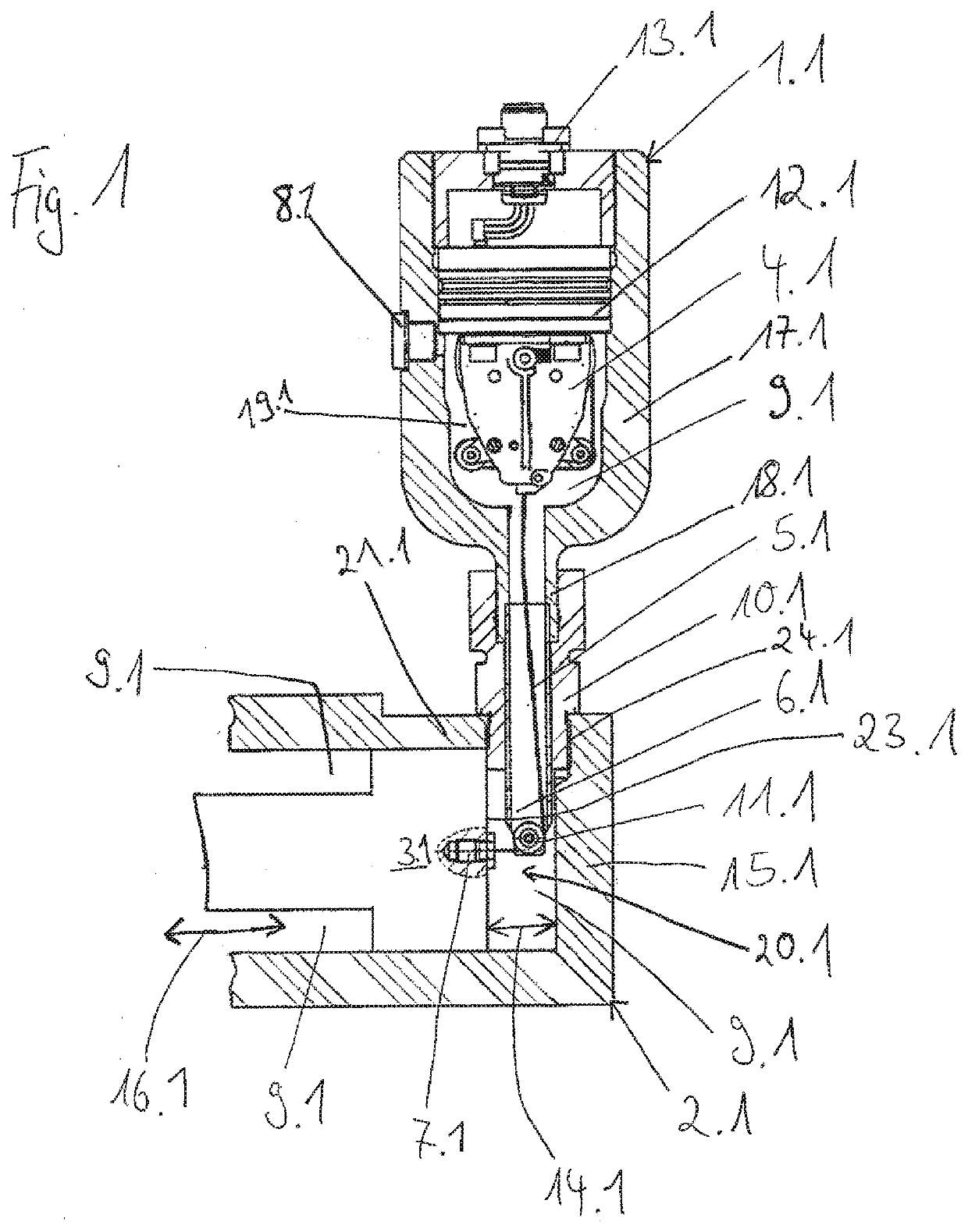
[0030]FIG. 1 shows an embodiment of a position sensor 1.1 according to the invention with a working cylinder 2.1. This position sensor 1.1 is shaped like a bottle or cartridge. The position sensor 1.1 is arranged laterally on a working cylinder 2.1 in the area of a cylinder head 15.1, whereby laterally means orthogonal to a piston stroke direction 16.1 of a piston 3.1 of the working cylinder 2.1. The position sensor 1.1 is connected to the working cylinder 2.1 by a flange 10.1. Both the flange 10.1 and a sensor arm 6.1 of the position sensor 1.1 passes trough a working cylinder wall 21.1 of working cylinder 2.1. For this purpose a bore 24.1 in the working cylinder wall 21.1 is included.

[0031]Inside the position sensor 1.1, a cable drum 4.1 is arranged on a seal 12.1 in a pressure room 19.1 in the direction of a bottleneck area 18.1. This pressure room 19.1 is limited by the seal 12.1 in the direction of an interface 13.1, which is located on the side of the seal facing away from the...


PUM


Abstract

A position sensor (1.1, 1.2) for a working cylinder (2.1, 2.2) with a cable drum (4.1, 4.2), a cable (5) with a piston anchor (7.1, 7.2) and an interface (13.1, 13.2) for determining a position and a movement of a piston (3.1, 3.2) of the working cylinder (2.1, 2.2), the position sensor (1.1, 1.2) is to be operatively connected to the working cylinder (2.1, 2.2) from outside in the area of a cylinder head (15.1, 15.2).

Description

TECHNICAL FIELD[0001]The present invention relates to a position sensor for working cylinders.BACKGROUND OF THE INVENTION[0002]Position sensors for working cylinders are already known and used in many different forms and designs. For example, common position sensors for working cylinders are known in which a position sensor is integrated in the area of a cylinder head in the working cylinder in the piston stroke direction. Such a design is still associated with a large stroke loss and is space-consuming. In addition, the working cylinder is significantly extended by this design. For example, the DE 20 2006 012 815 U1 should be mentioned here, which reveals a path length sensor which is particularly suitable for use in the inside of a working cylinder. Furthermore, the DE 43 06 539 C2 is to be mentioned, in which an arrangement for detecting the position of a piston in a working cylinder is detected.SUMMARY OF THE INVENTION[0003]The object of the present invention is to overcome the ...

Claims


Application Information

Patent Timeline
IPC IPC(8): F15B15/28
CPCF15B15/2892F15B15/2823F15B15/283G01B3/11
Inventor THOMA, HANSPETERREICHLE, JOACHIMROTH, MATTHIAS
Owner SIKO
Why Eureka
Try Eureka