Reservoir tank

a technology of reserve tanks and tanks, applied in the field of reserve tanks, can solve problems such as the reduction of cooling efficiency

Inactive Publication Date: 2021-01-07
TAIGAASU HORIMAA
View PDF0 Cites 4 Cited by
  • Summary
  • Abstract
  • Description
  • Claims
  • Application Information

AI Technical Summary

Benefits of technology

[0036]Furthermore, with the reservoir tank according to the eighth aspect, it is possible to circulate the cooling fluid from which the bubbles have been removed to the discharge pipe from the suction hole while feeding the cooling fluid containing the bubbles into the tank chamber. Therefore, the gas-liquid separation effect can be further enhanced.

Problems solved by technology

When air bubbles are generated in the cooling fluid, cooling efficiency may decrease.

Method used


Image

  • Reservoir tank
  • Reservoir tank
  • Reservoir tank

Examples


first embodiment

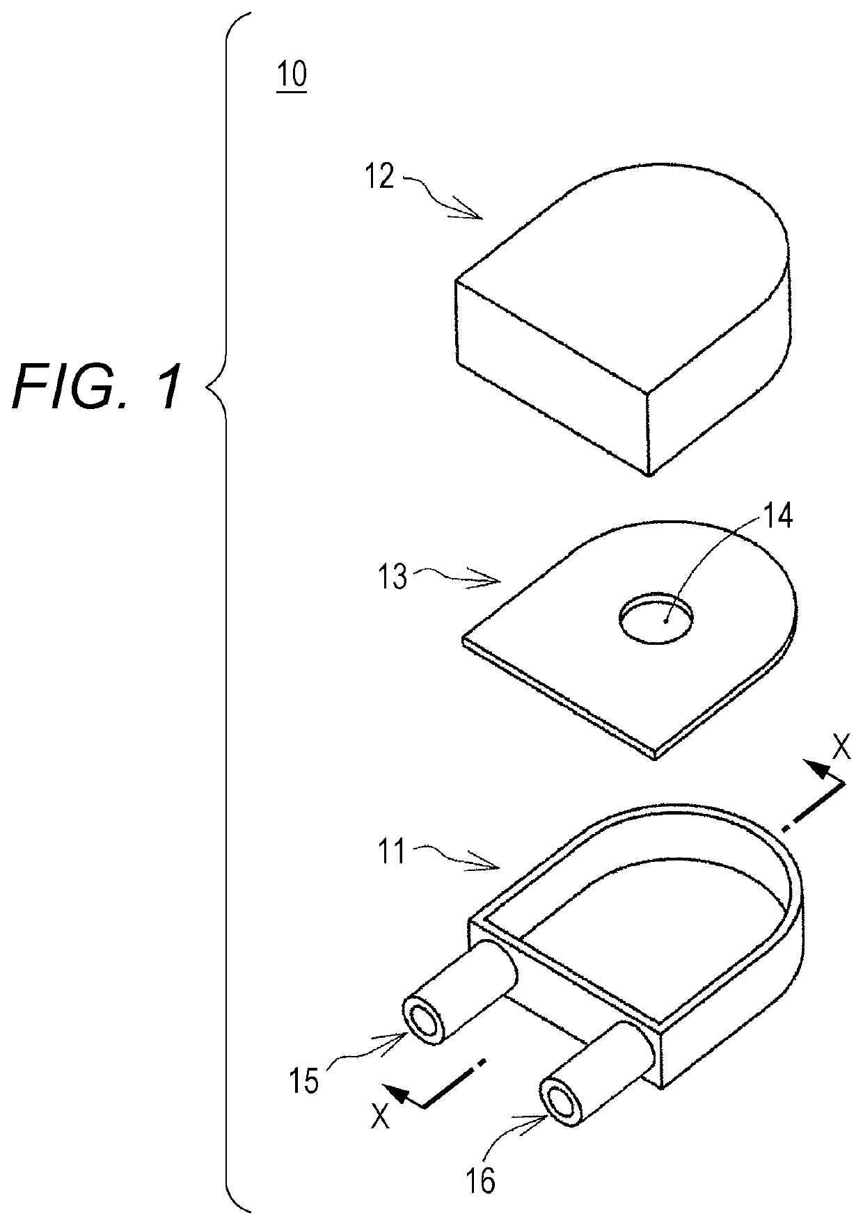
[0038]FIGS. 1, 2 and 3 illustrate a structure of a reservoir tank 10 of a FIG. 1 illustrates main members of the reservoir tank 10 in an exploded state using a perspective view. The reservoir tank 10 is configured to include a hollow tank, and an inflow pipe 15 and a discharge pipe 16 connected to the tank. The reservoir tank 10 used in a cooling fluid circuit of the liquid-cooled cooling system is disposed and connected in the cooling fluid circuit of the liquid-cooled cooling system so that the cooling fluid flows from the inflow pipe 15 into the hollow tank, and the cooling fluid flows out of the hollow tank through the discharge pipe 16.

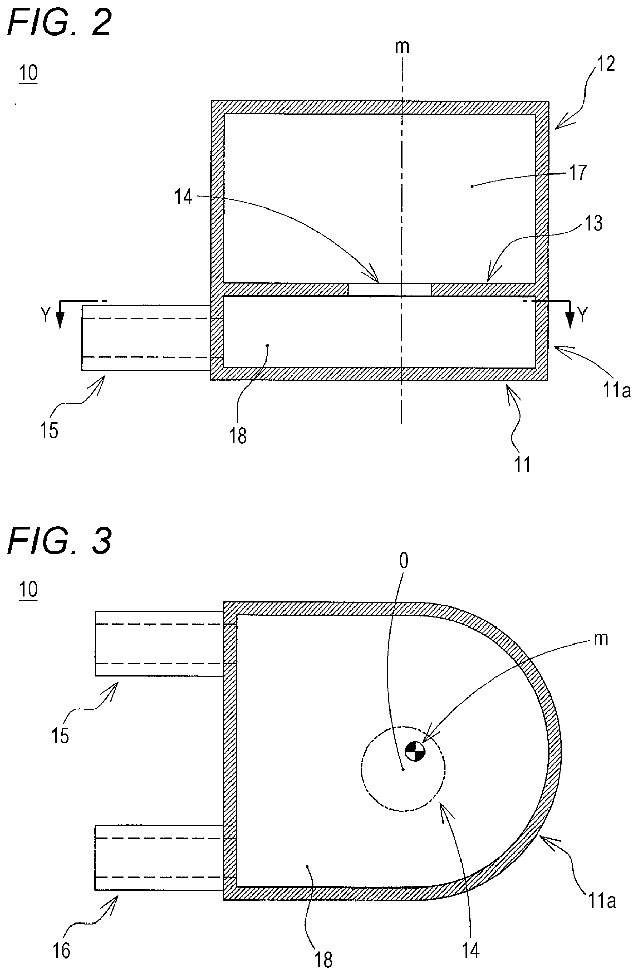
[0039]FIG. 2 is a cross-sectional view illustrating a cross-section of the reservoir tank 10 taken along a vertical plane including a line X-X (X-X axis) in FIG. 1. An upper side in FIG. 2 corresponds to the upper side in the vertical direction. FIG. 3 is a cross-sectional view illustrating a cross-section of the reservoir tank 10 taken along a ...

second embodiment

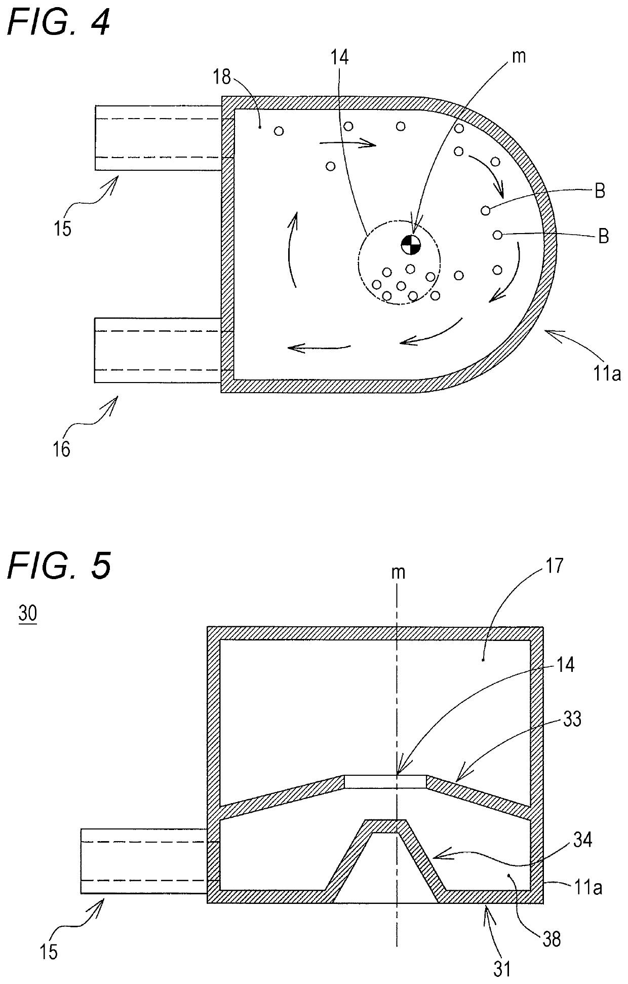
[0065]In the reservoir tank 30 of the second embodiment, the partition wall 33 is provided to have a conical surface shape that goes vertically upward as it goes to the communication hole 14 from the outer peripheral portion of the partition wall 33.

[0066]With the partition wall 33 having such a structure, in the gas-liquid separation chamber 38, the air bubbles collected in a central portion of the gas-liquid separation chamber 38 are guided by the partition wall 33 having a conical surface shape, and easily flow to the upper tank chamber 17. Thus, the gas-liquid separation effect can be enhanced.

[0067]In the reservoir tank 30 of the second embodiment, the bottom surface 31 located vertically below the gas-liquid separation chamber 38 is provided with a conical surface 34 going vertically upward as it goes to the central axis m of the cylindrical outer peripheral wall 11a from the cylindrical outer peripheral wall 11a. The conical surface 34 is preferably provided below the communi...

third embodiment

[0070]FIGS. 6, 7, 8 and 9 illustrate a reservoir tank 21 according to a The structure of the reservoir tank 21 is illustrated in an exploded perspective view of FIG. 6, a cross-sectional view taken along a line X-X (see FIG. 6) of FIG. 7, and a cross-sectional view taken along a line Y-Y (see FIG. 7) of FIG. 8. FIG. 9 illustrates a gas-liquid separation operation of the reservoir tank 21.

[0071]The reservoir tank 21 of the third embodiment has a curved channel 29 as compared with the reservoir tank 10 of the first embodiment. That is, the reservoir tank 21 has a structure, in which the gas-liquid separation chamber 18 in the structure of the reservoir tank 10 of the first embodiment is replaced with the curved channel 29. Other structures of the reservoir tank 21 are the same as those of the reservoir tank 10 of the first embodiment.

[0072]The reservoir tank 21 of the third embodiment includes the tank chamber 17 for storing the cooling fluid and the air, the curved channel 29 provid...


PUM

PropertyMeasurementUnit
angle of flowaaaaaaaaaa
conical surface shapeaaaaaaaaaa

Abstract

A reservoir tank includes: a tank chamber for storing a cooling fluid; a gas-liquid separation chamber provided adjacently below the tank chamber in a vertical direction; a partition wall for partitioning the tank chamber and the gas-liquid separation chamber; an inflow pipe for sending the cooling fluid into the reservoir tank; and a discharge pipe for discharging the cooling fluid from the reservoir tank. The inflow pipe and the discharge pipe are connected to the gas-liquid separation chamber, the gas-liquid separation chamber has a cylindrical outer peripheral wall, the cooling fluid sent in from the inflow pipe to the gas-liquid separation chamber flows along the cylindrical outer peripheral wall in a curved manner so as to rotate around a vertical axis, and is guided to the discharge pipe, the partition wall is provided with a communication hole communicating the tank chamber with the gas-liquid separation chamber, and the communication hole is provided at a position closer to a central axis of the cylindrical outer peripheral wall than to the cylindrical outer peripheral wall when viewed in the vertical direction.

Description

CROSS-REFERENCE TO RELATED APPLICATION[0001]This application claims priority from Japanese Patent Application No. 2019-123092 filed with the Japan Patent Office on Jul. 1, 2019, and from Japanese Patent Application No. 2019-128688 filed with the Japan Patent Office on Jul. 10, 2019, the entire contents of both of which are hereby incorporated by reference.BACKGROUND1. Technical Field[0002]One aspect of the present disclosure relates to a reservoir tank.2. Description of the Related Art[0003]Liquid-cooled cooling systems are used for cooling internal combustion engines, electric elements, electronic boards, and the like. In the liquid-cooled cooling system, heat is collected from a member to be cooled by circulating a cooling fluid, and the member to be cooled is cooled by dissipating heat from a heat radiator. In the liquid-cooled cooling system, a cooling fluid tank, that is, the reservoir tank, may be provided in a cooling fluid circuit for circulating the cooling fluid. The reser...

Claims


Application Information

Patent Timeline
Patent Type & Authority Applications(United States)
IPC IPC(8): B04C1/00F28F13/00B01D19/00
CPCB04C1/00B01D19/0057F28F13/00F01P11/00F01P11/028F01P11/029F28F2265/18H05K7/20272
Inventor SAKATA, SHUNSUKETSUGUI, EIJI
Owner TAIGAASU HORIMAA
Why Eureka
Try Eureka