Gas-liquid separation device and hard surface cleaner with same

A technology of a gas-liquid separation device and a cleaner, applied in the field of cleaners, can solve the problems of limited inclination angle of the suction device, unfavorable production efficiency, inconvenient processing and production, etc., achieve good gas-liquid separation effect, save volume and space, The effect of simplifying the internal structure

Inactive Publication Date: 2014-03-26
NINGBO LUCKY SNOW MECHANICAL EQUIP MFG & TRADING
View PDF10 Cites 5 Cited by
  • Summary
  • Abstract
  • Description
  • Claims
  • Application Information

AI Technical Summary

Problems solved by technology

But such a hard surface cleaner, its separation device and dirty liquid tank are separately arranged, so that the parts in the whole suction device are set relatively crowded, so its dirty liquid tank and storage area are all small, and the dirty water that can be accommodated Less, and the storage area is used to hold less dirty water when the suction device is tilted, so the angle of inclination of the suction device is limited, and dirty water needs to be cleaned frequently, which is very inconvenient to use
Moreover, such a suction device has a complex structure, and it is very inconvenient to process and produce, especially the mutual position setting of the suction port, the separation device, the dirty liquid tank and the suction device needs to meet higher conditions, otherwise it will cause Poor suction or unsuccessful gas-liquid separation makes processing more difficult, which is not conducive to improving production efficiency and increasing output

Method used


Image

  • Gas-liquid separation device and hard surface cleaner with same
  • Gas-liquid separation device and hard surface cleaner with same
  • Gas-liquid separation device and hard surface cleaner with same

Examples


Embodiment Construction

[0030] The present invention will be further described in detail below in conjunction with the accompanying drawings and embodiments.

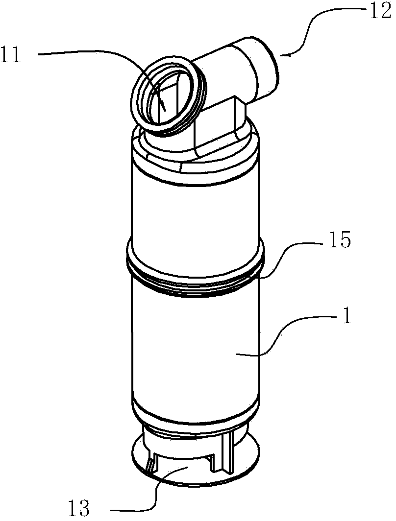
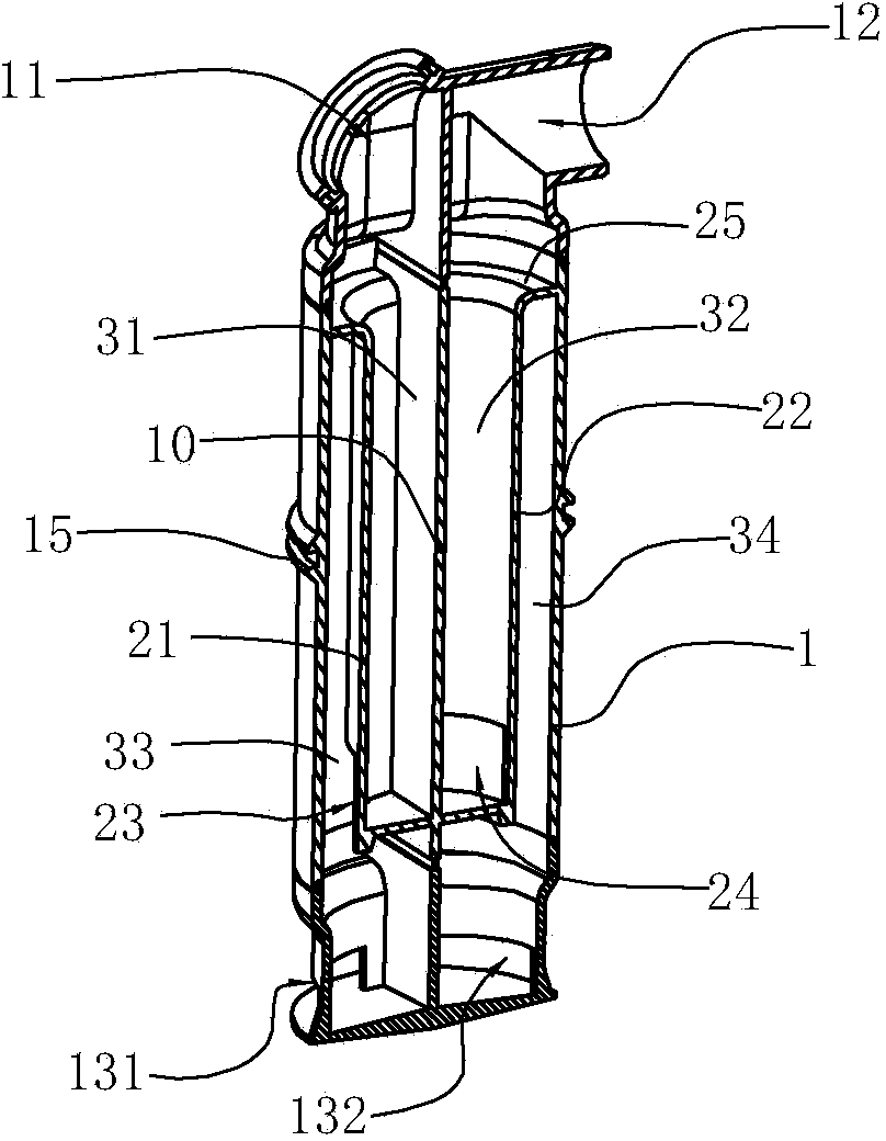
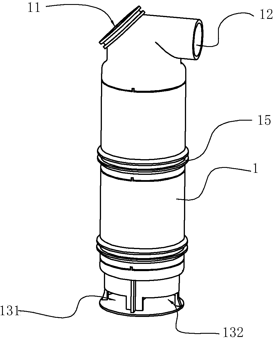
[0031] Such as figure 1 , 2 Shown is the first embodiment of the gas-liquid separation device of the present invention. The gas-liquid separation device is a hollow cylindrical closed part, including a housing 1, and the top of the housing 1 is provided with two openings, which are respectively an air inlet 11 and an air suction port 12, the air inlet 11 and the air suction port. The air ports 12 are respectively arranged on both sides of the top of the casing 1, and the bottom side of the casing 1 is provided with a water outlet. In the hard surface cleaner, the dirty water sucked in from the air inlet 11 passes through the casing 1 and then enters the water tank from the water outlet 13 on the bottom side of the casing, the lower part of the gas-liquid separation device is located in the water tank and passes through the water outlet 13 i...


PUM


Abstract

The invention provides a gas-liquid separation device and a hard surface cleaner with the gas-liquid separation device. The gas-liquid separation device comprises a shell. The bottom end of the shell is sealed, an air inlet and an air suction port are formed in the two sides of the top end of the shell respectively, the internal space of the shell is divided by a middle board into two side spaces which are not communicated, the two side spaces are respectively provided with at least one separating board, the internal space of the shell is divided into buffer zones and storage zones through the separating boards in the radial direction of the space, each buffer zone and the storage zone located in the same side are communicated through an opening formed in the side face of the bottom of the corresponding separating board, the storage space of each layer is communicated with the buffer space of the lower layer at the same side, the side face of the bottom of the portion, corresponding to the storage space on the lowest layer, of the shell is provided with a water outlet communicated with the external environment. According to the gas-liquid separation device and the hard surface cleaner with the gas-liquid separation device, the gas-liquid separation function and the anti-toppling and anti-backward-flow function are achieved, the structure is simple, the gas-liquid separation effect is good, the machining efficiency, the production efficiency and the assembly efficiency are extremely high, and the volume and the space are saved.

Description

technical field [0001] The invention relates to a gas-liquid separation device and a cleaner with the gas-liquid separation device, in particular to a hard surface cleaner with the gas-liquid separation device. Background technique [0002] For some hard surfaces such as glass, walls, floors, etc., the method of manual wiping is usually used for cleaning, which is not only time-consuming and laborious, but also has extremely low work efficiency, high labor intensity, and the cleaning effect is relatively general. Therefore, many hard surface cleaners have appeared now to clean hard surfaces such as glass and walls. Generally, the main principle of this kind of hard surface cleaner is to use the suction unit to generate suction airflow, so that dust and small water droplets can be sucked from the hard surface through the suction nozzle, and the dust and small water droplets can be transferred to the dirty liquid tank . [0003] For example, US Pat. No. 6,347,428 discloses a...

Claims


Application Information

Patent Timeline
Patent Type & Authority Applications(China)
IPC IPC(8): A47L11/29A47L11/40B01D45/00
CPCA47L7/00A47L7/0023A47L7/0004A47L1/05
Inventor 高琴君
Owner NINGBO LUCKY SNOW MECHANICAL EQUIP MFG & TRADING
Why Eureka
Try Eureka