
Gas-liquid separator

a gas-liquid separator and separator technology, which is applied in the direction of separation processes, electrochemical generators, transportation hydrogen technology, etc., can solve the problems of difficult flow of fuel exhaust gas, and achieve the effect of promoting gas-liquid separation, facilitating equipment layout, and continuing steady operation of fuel cells

Active Publication Date: 2018-12-27
HONDA MOTOR CO LTD
View PDF1 Cites 5 Cited by
  • Summary
  • Abstract
  • Description
  • Claims
  • Application Information

AI Technical Summary

Benefits of technology

The present invention provides a gas-liquid separator that allows easy inward flow of gas and liquid even when the separator is in an inclined posture. This prevents the inlet port from being blocked or closed by the stored liquid, allowing for continued operation of the fuel cell system.

Problems solved by technology

When such a state occurs, it becomes difficult for the fuel exhaust gas to flow into the gas-liquid separator from the inlet port.

Method used


Image

  • Gas-liquid separator
  • Gas-liquid separator
  • Gas-liquid separator

Examples


Embodiment Construction

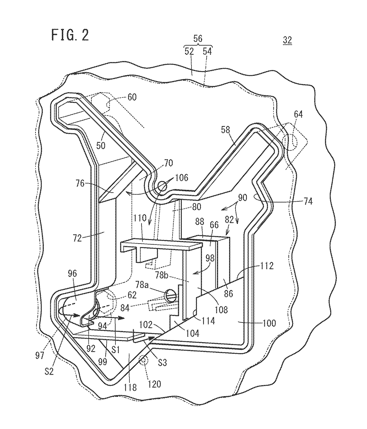
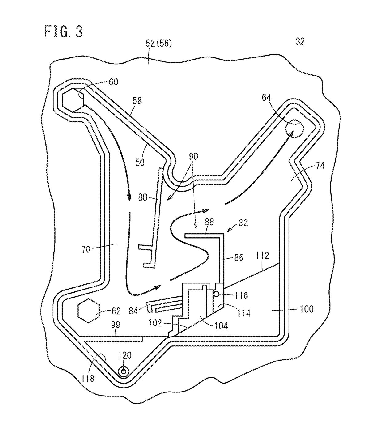
[0029]A preferred embodiment of a gas-liquid separator according to the present invention will be described in detail below with reference to the accompanying drawings. In the present embodiment, a case is exemplified in which the gas-liquid separator is attached to a fuel cell to thereby constitute a fuel cell system. Further, in the following description, up, down, left, and right orientations of the gas-liquid separator correspond to the up, down, left, and right directions shown in FIG. 2, but this is simply for the sake of convenience and to facilitate understanding. In particular, the illustrated left and right directions do not necessarily specify the left and right directions when the gas-liquid separator is actually used.

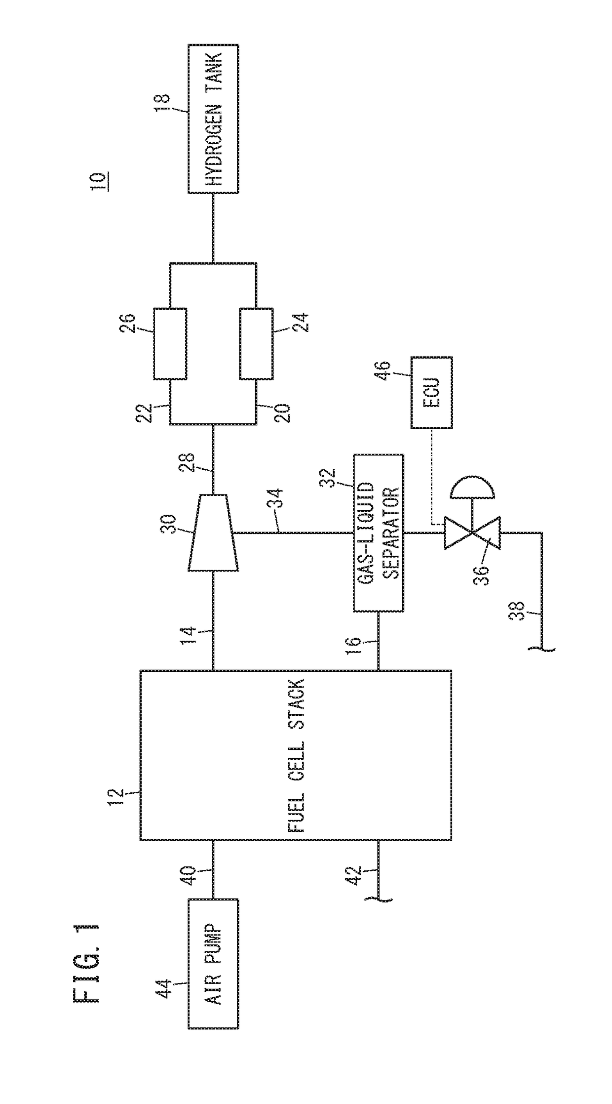
[0030]Initially, the fuel cell system will be described briefly with reference to FIG. 1. A fuel cell system 10 is an in-vehicle type of fuel cell system which is installed in a fuel cell vehicle (not shown) such as a fuel cell electric vehicle or the like....


PUM

PropertyMeasurementUnit
sizeaaaaaaaaaa
liquid surface levelaaaaaaaaaa
timeaaaaaaaaaa

Abstract

A gas-liquid separator includes a casing in which there are formed an inlet port to which a gas-liquid two-phase flow is supplied, and an outlet port through which a gas flow is discharged after the gas-liquid two-phase flow has been separated into a gas and a liquid. A gas-liquid separation chamber is formed in the casing by a partition wall. The inlet port opens on a surface of the partition wall in the gas-liquid separation chamber. The gas-liquid separator further includes a deflection member configured to change a flow direction of the gas-liquid two-phase flow that flows in from the inlet port, and a clearance is formed between the deflection member and an inner wall of the casing.

Description

CROSS-REFERENCE TO RELATED APPLICATION[0001]This application is based upon and claims the benefit of priority from Japanese Patent Application No. 2017-122258 filed on Jun. 22, 2017, the contents of which are incorporated herein by reference.BACKGROUND OF THE INVENTIONField of the Invention[0002]The present invention relates to a gas-liquid separator, and more particularly, to a gas-liquid separator suitable for attachment to a fuel cell.Description of the Related Art[0003]As is well known, a fuel cell includes an anode and a cathode which face toward one another with an electrolyte (for example, a solid polymer membrane) being sandwiched therebetween. A fuel gas such as hydrogen is supplied to the anode, and an oxygen containing gas such as compressed air is supplied to the cathode to thereby generate electricity. At least a part of the fuel gas and the oxygen containing gas are consumed. However, unreacted components thereof are discharged as fuel exhaust gas and oxygen containing...

Claims


Application Information

Patent Timeline
Patent Type & Authority Applications(United States)
IPC IPC(8): H01M8/04119B01D45/08
CPCH01M8/04164B01D45/08H01M2250/20Y02E60/50Y02T90/40
Inventor OKAMURA, YUJIFUKUDA, TETSUYASAITO, YOICHIRO
Owner HONDA MOTOR CO LTD
Learn More