
Aircraft engine and air-oil separator system therefore

Active Publication Date: 2021-01-07
PRATT & WHITNEY CANADA CORP
View PDF0 Cites 1 Cited by
  • Summary
  • Abstract
  • Description
  • Claims
  • Application Information

AI Technical Summary

Benefits of technology

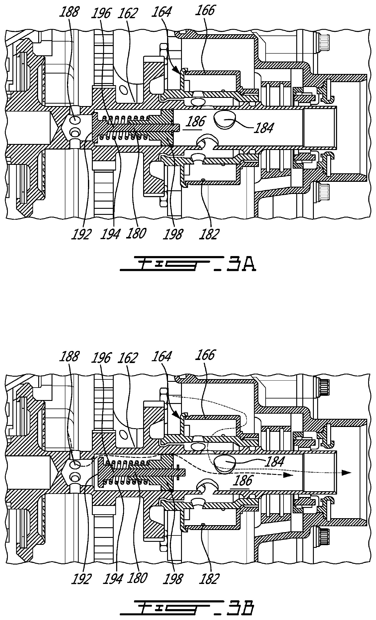
The technical effects of this patent include: providing an air-oil separator with a pressure relief valve to prevent damage to the aircraft engine caused by high pressure, and a rotary shaft and annular housing for collecting and separating air-oil mixture. Additionally, the patent describes a method of evacuating pressure from an accessory gearbox of a gas turbine engine by conveying the air-oil mixture across the separator media and then through the pressure relief valve until the pressure becomes weaker than the biasing force of the valve.

Problems solved by technology

If the air-oil separator is in an accessory gearbox for instance, this can lead to an undesired increase in pressure in the accessory gearbox.
Increasing the capacity of the air-oil separator can alleviate this issue, but at the expense of an increase in weight and / or cost.

Method used


Image

  • Aircraft engine and air-oil separator system therefore
  • Aircraft engine and air-oil separator system therefore
  • Aircraft engine and air-oil separator system therefore

Examples


Embodiment Construction

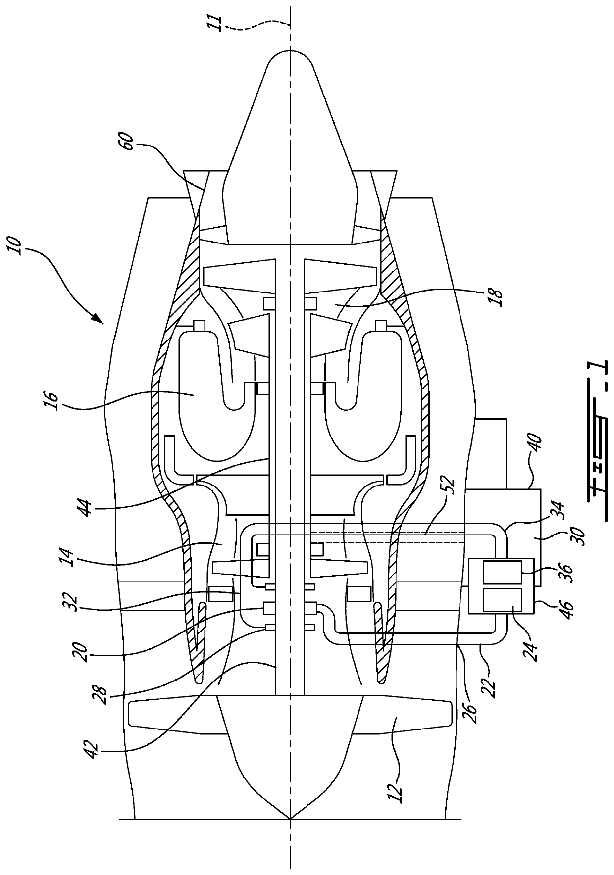
[0013]FIG. 1 illustrated a gas turbine engine 10 of a type preferably provided for use in subsonic flight, generally comprising in serial flow communication a fan 12 through which ambient air is propelled, a compressor section 14 for pressurizing the air, a combustor 16 in which the compressed air is mixed with fuel and ignited for generating an annular stream of hot combustion gases, and a turbine section 18 for extracting energy from the combustion gases.

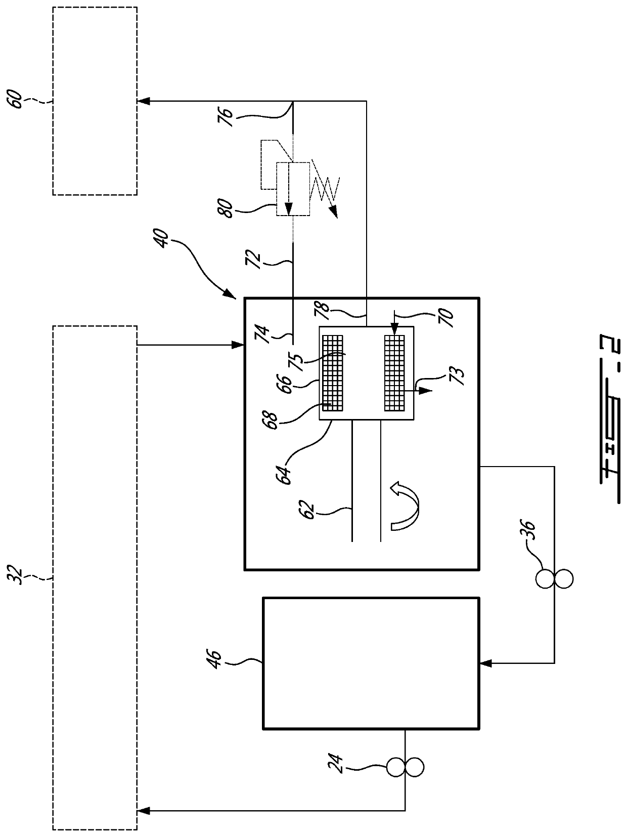
[0014]The compressor 14, fan 12 and turbine 18 have rotating components which can be mounted on one or more shafts. Bearings 20 are used to provide smooth relative rotation between a shaft and casing (non-rotating component), and / or between two shafts which rotate at different speeds. An oil lubrication system 22 including an oil pump 24, sometimes referred to as a main pump, and a network of conduits and nozzles 26, is provided to feed the bearings 20 with oil. Seals 28 are used to contain the oil. A scavenge system 30 having cav...


PUM

PropertyMeasurementUnit
Pressureaaaaaaaaaa

Abstract

The aircraft engine can have an air-oil separator having an air-oil mixture inlet, an oil outlet, an air outlet, and a pressure relief path provided fluidly in parallel with the air-oil separator, between the air-oil mixture inlet and the air outlet, the pressure relief path can have a pressure relief valve for evacuating air-oil mixture to the exhaust duct in the event of excess pressure in the auxiliary gearbox.

Description

TECHNICAL FIELD[0001]The application related generally to gas turbine engines and, more particularly, to air-oil separators thereof.BACKGROUND OF THE ART[0002]In certain operating conditions, the flow through the air-oil separator can exceed capacity. If the air-oil separator is in an accessory gearbox for instance, this can lead to an undesired increase in pressure in the accessory gearbox. Increasing the capacity of the air-oil separator can alleviate this issue, but at the expense of an increase in weight and / or cost. Accordingly, there remained room for improvement.SUMMARY[0003]In one aspect, there is provided an aircraft engine comprising an air-oil separator having an air-oil mixture inlet, an oil outlet, an air outlet, and a pressure relief path provided fluidly in parallel with the air-oil separator, between the air-oil mixture inlet and the air outlet, the pressure relief path having a pressure relief valve.[0004]In another aspect, there is provided an air-oil separator for...

Claims


Application Information

Patent Timeline
IPC IPC(8): F16H57/04F02C7/32F02C7/06F16H57/027B64D33/00
CPCF16H57/0404F02C7/32F16H2057/02043F16H57/027B64D33/00F02C7/06F01D25/18F05D2260/609F05D2260/98F16N39/002F16N2039/007F16N2210/02B01D45/12F05D2260/608
Inventor KOSTKA, RICHARDMENHEERE, DAVID
Owner PRATT & WHITNEY CANADA CORP
Learn More