Centrifuge Rotor, Holding Crown And Holding Crown Arrangement Therefor, And Centrifuge

a centrifuge and rotor technology, applied in the direction of centrifuges, etc., can solve the problems of reusing bottles, wasting time and money, and separating bags from the bag system before centrifugation, and achieve the effect of saving time and money

Pending Publication Date: 2021-01-21
THERMO ELECTRONICS LED GMBH
View PDF2 Cites 2 Cited by
  • Summary
  • Abstract
  • Description
  • Claims
  • Application Information

AI Technical Summary

Benefits of technology

[0025]Correspondingly, the centrifuge rotor according to the present invention and the holding crown used therein enable centrifugation of sample containers with tubes protruding outward without having to take special measures such as disconnecting the tubes. Sample containers that can be centrifuged with the aid of the centrifuge rotor according to the present invention or a centrifuge rotor comprising this centrifuge rotor include, in particular, the following: a bottle which can be closed by a cap, wherein the at least one tube is guided through an opening in the cap; a film bag in which one end of the at least one tube is sealed, in particular glued or welded; an arrangement of a plurality of film bags, in each of which one end of at least one tube is sealed, in particular glued or welded, wherein the other ends of the tubes are connected to one another. In particular, those sample container systems can be centrifuged which are described in German Patent Application No. 102018001675.8 and International Patent Application No. PCT/IB2019/051639. Reference is hereby expressly made to these two patent applications and their content is hereby incorporated into this application. The bag systems described can be centrifuged together with the branched tube assembly. Under certain circumstances, only the common supp

Problems solved by technology

While the cap provided with the connecting tube can be disposed of after use, the problem of sterilizing the bottle for reuse remains.
However, separating the bags from the bag system before centrifuging and, if necessary, recombining the bags into a bag system after centrifuging are costly and time-consuming.
This means that part of the time saved by filling the bags together is eaten up again.
However, centrifuging the bag system without

Method used


Image

  • Centrifuge Rotor, Holding Crown And Holding Crown Arrangement Therefor, And Centrifuge
  • Centrifuge Rotor, Holding Crown And Holding Crown Arrangement Therefor, And Centrifuge
  • Centrifuge Rotor, Holding Crown And Holding Crown Arrangement Therefor, And Centrifuge

Examples


Embodiment Construction

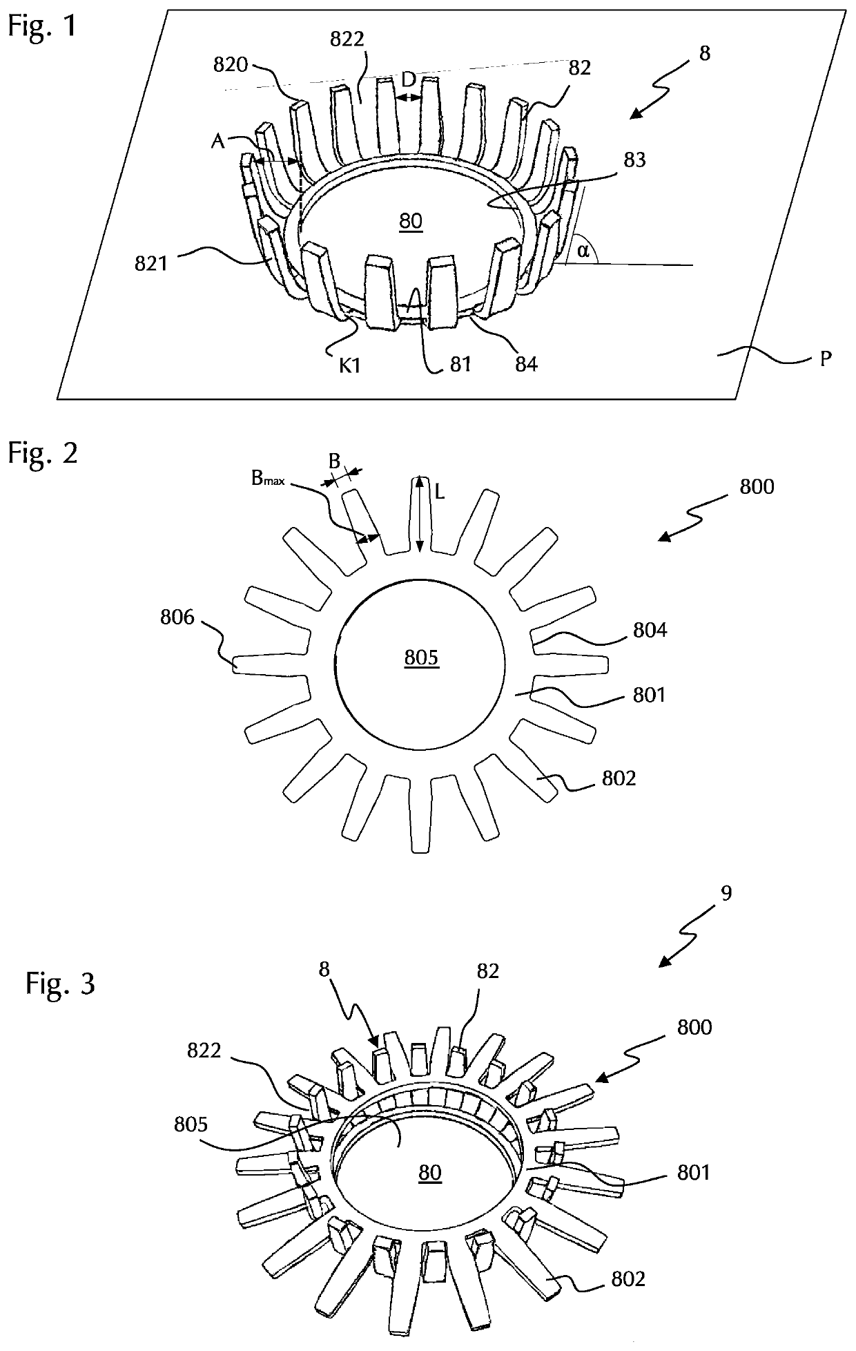
[0046]FIG. 1 shows a first embodiment of a holding crown 8 according to the present invention in a perspective view. The holding crown 8 may be made of a metal, in particular aluminum or steel, in particular spring steel, or a plastic. It has an annular base body 81, which is flat and extends with its invisible underside in a plane P which forms the contact surface of the base body. The base body 81 has an inner edge 83 which surrounds a circular central opening 80. A plurality of prongs 82, in this case 18 prongs, extend in a uniform distribution around the outer circumference away from the outer edge 84. All prongs 82 are of the same design, i.e., they have the same shape and the same dimensions. In the region of their respective connection to the base body 81, the prongs 82 have a bend K1. This has the shape of a rounded bend, which is designed such that the bent regions 821 of the prongs 82 adjoining the bend K1 run outward and upward from the base body 81. The angle α by which ...


PUM


Abstract

The present invention relates to a centrifuge rotor with a rotor body and a receptacle arranged centrally therein for receiving a drive head of a drive shaft of a centrifuge which can be rotated about an axis of rotation (R), and sample receptacles for accommodating a plurality of sample containers. A holding crown is arranged on a top side (O) of the rotor body facing away from an insertion side (E) of the drive head, said holding crown having an annular base body, which encloses a central opening, and prongs extending upward away from the top side (O), wherein the holding crown is arranged in such a way that the axis of rotation (R) runs through the central opening. The present invention further relates to a holding crown for use with a centrifuge rotor and having an annular base body enclosing a central opening and prongs emanating from the base body and extending upward, wherein the prongs are offset at least in the region of their free ends by a spacing (A) from an inner edge of the base body. The present invention further relates to a holding crown arrangement comprising the holding crown, and a centrifuge comprising the centrifuge rotor, the holding crown or the holding crown arrangement.

Description

CROSS-REFERENCE TO RELATED APPLICATION[0001]The present application claims priority under 35 U.S.C. § 119 of German Patent Application No. 102019004958.6, filed Jul. 16, 2019, the disclosure of which is hereby incorporated herein by reference in its entirety.FIELD OF THE INVENTION[0002]The present invention relates to a centrifuge rotor and a centrifuge comprising a rotor, in particular a laboratory centrifuge.BACKGROUND OF THE INVENTION[0003]Centrifuges are used in laboratories to separate mixtures of substances into their constituents using centrifugal force. In many applications, the mixtures of substances are biological or microbiological samples. One example is cell suspensions, which come from fermentation tanks, bioreactors or similar containers, for example, and which are to be divided into their constituents by centrifugation. Before centrifuging, the cell suspension must be transferred from the container into suitable sample containers in which they can be centrifuged. An ...

Claims


Application Information

Patent Timeline
IPC IPC(8): B04B7/08B04B5/04
CPCB04B7/08B04B2005/0435B04B5/0407B04B5/0428B04B7/00B04B5/0414B04B5/0421
Inventor BALLHAUSE, NORMANHINZ, ROMANAROTHER, JAN
Owner THERMO ELECTRONICS LED GMBH
Why Eureka
Try Eureka