Integrated charger and motor control system

a technology of motor control system and charger, applied in the direction of hybrid vehicles, propulsion by batteries/cells, transportation and packaging, etc., can solve the problem of potential danger of electric power converter, and achieve the effect of maximizing power conversion efficiency

Active Publication Date: 2021-01-21
HUAWEI DIGITAL POWER TECH CO LTD
View PDF0 Cites 4 Cited by
  • Summary
  • Abstract
  • Description
  • Claims
  • Application Information

AI Technical Summary

Benefits of technology

[0011]Optionally, in any of the preceding aspects, the apparatus includes a processor coupled to the first, second, and third power converter stages to select a con

Problems solved by technology

Electric power converters are potentially d

Method used


Image

  • Integrated charger and motor control system
  • Integrated charger and motor control system
  • Integrated charger and motor control system

Examples


Embodiment Construction

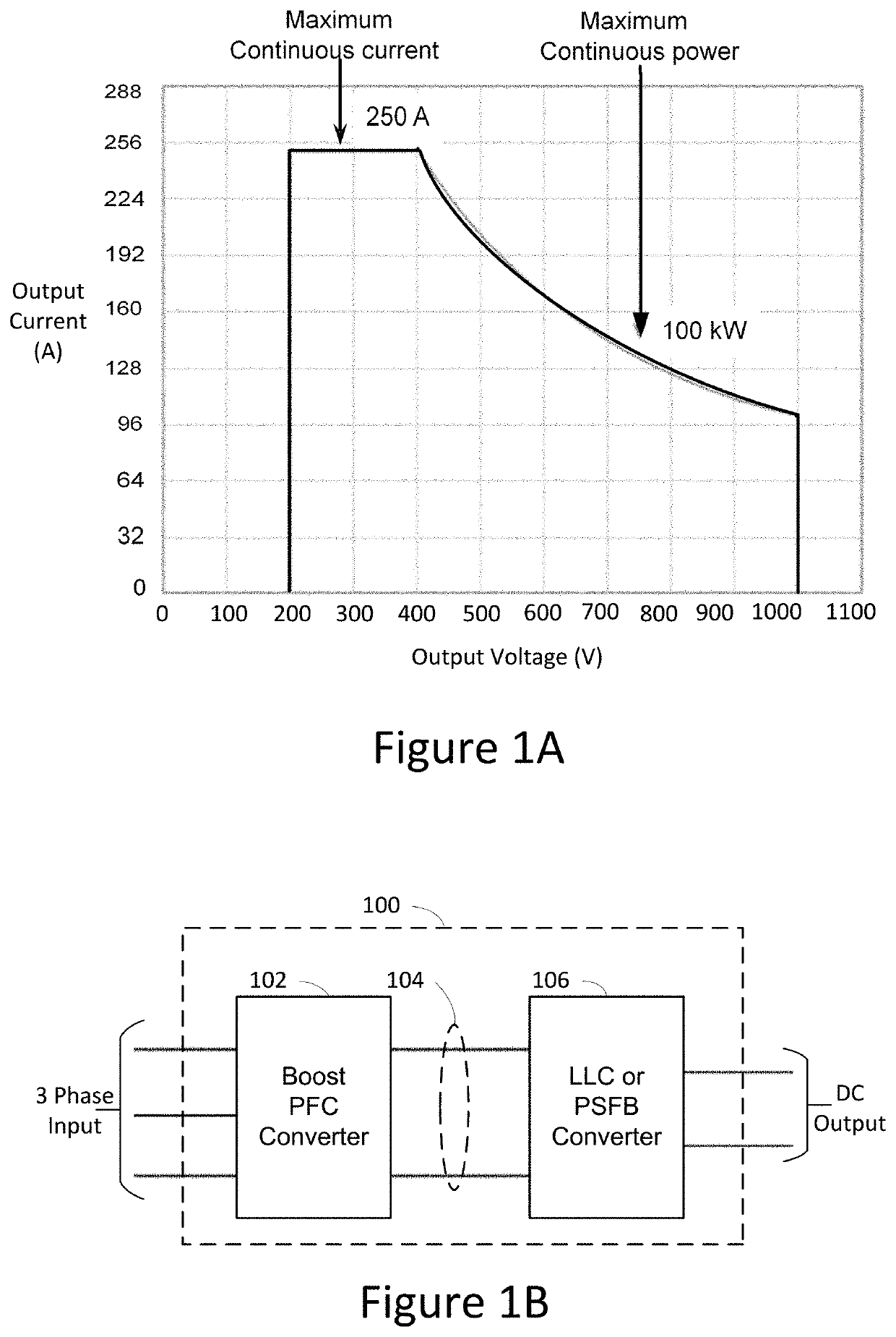
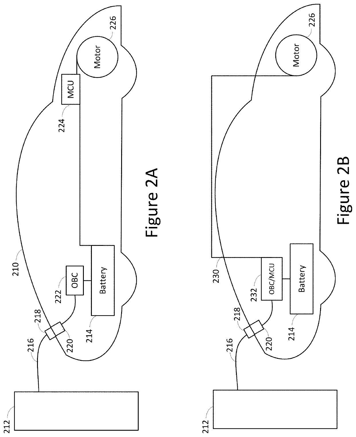
[0043]The present disclosure will now be described with reference to the figures, which in general relate to electric power circuits that may be used, for example, in an electric vehicle. For example, circuits described here may be used for charging a battery from an external source and for controlling power to an electric motor from the battery. Using shared circuitry to perform such different functions is efficient and may save cost. Examples include using a three-port power converter that includes three power converter stages coupled to a transformer module to transfer power between three ports (e.g. ports for external power, a battery, and an electric motor of an electric vehicle). The three power converter stages may be configured to transfer and convert power between any two ports in an efficient and adaptive manner.

[0044]In an electric vehicle, a three-port power converter may be used to convert power received from an external power source (e.g. charging station) to a suitabl...


PUM


Abstract

According to one aspect of the present disclosure, there is provided an apparatus that includes first, second, and third power converter stages connected to a transformer module. At least one of the first, second, and third power converter stages is a multi-level power converter stage that has multiple configurations to generate different output voltages from an input voltage.

Description

CLAIM OF PRIORITY[0001]This application is a continuation of and claims the benefit of priority to International Application No. PCT / US2019 / 034014, filed May 24, 2019, the entire contents of which are hereby incorporated by reference.FIELD[0002]The disclosure generally relates to the field of electric power circuits such as electric power circuits used in electric vehicles.BACKGROUND[0003]Electric power circuits include AC to DC power converters, as well as DC to DC power converters. Electric power converters have a wide range of uses including, but not limited to, use in an On-Board Charger (OBC) to charge a battery of an Electric Vehicle (EV). Electric power converters are potentially dangerous due to high voltages and currents. Isolation may reduce danger and may be required by some safety standards.[0004]An electric motor, such as a motor of an EV, may be controlled by a Motor Control Unit (MCU). For example, an MCU may control an electric current from a battery to an electric m...

Claims


Application Information

Patent Timeline
IPC IPC(8): B60L53/22B60L50/61
CPCB60L53/22B60L2210/14B60L2210/30B60L50/61H02M3/33561H02M1/4216H02M7/487H02M1/10H02M7/4807B60L53/24B60L2210/40H02J2207/20H02J2310/48H02J7/02H02J7/00714H02J7/0071Y02T10/62Y02T10/70Y02T10/72Y02T10/92Y02T10/7072Y02T90/14H02M1/0064H02M1/008H02M1/0093H02M1/0058H02M1/007H02M1/0085
Inventor ZHU, HUIBINDAI, HEPINGLIANG, YONGTAOLIU, WEIPING
Owner HUAWEI DIGITAL POWER TECH CO LTD
Why Eureka
Try Eureka