Compact membrane module system for gas separation

a technology of gas separation and membrane modules, applied in the separation process, membranes, dispersed particle separation, etc., can solve the problem that the series arrangement occupies considerably more space, and achieve the effect of reducing the weight of the membrane-based gas separation system, reducing the cost of acquisition and operation, and being convenient to configur

Active Publication Date: 2021-01-28
GENERON IGS
View PDF3 Cites 0 Cited by
  • Summary
  • Abstract
  • Description
  • Claims
  • Application Information

AI Technical Summary

Benefits of technology

[0024]The invention has the further object of providing a membrane-based gas-separation system which can be easily configured to provide either a moderate purity product gas, or a high purity product gas, simply by changing the positions of a small number of valves.
[0025]The invention has the further object of reducing the weight of a membrane-based gas-separation system.
[0026]The invention has the further object of reducing the cost of acquisition and operation of a membrane-based gas-separation system.
[0027]The invention has the further object of facilitating the production of either moderate purity nitrogen, or high purity nitrogen, using a set of gas-separation membrane modules contained in a single housing.
[0028]The invention has the further object of facilitating the connection of gas separation modules to inlet and outlet manifolds, by providing slotted or perforated pipes, each of which provides a path for gas flowing between a module and a manifold.
[0029]The invention has the further object of making it easy to remove one or more modules from the system, by temporarily blocking the flow of gas at the inlet and outlet ends of a module.

Problems solved by technology

Moreover, the series arrangement typically occupies considerably more space than does the set of parallel modules, because of the need to provide distinct stages which are separate from each other, each stage having its own housing.

Method used


Image

  • Compact membrane module system for gas separation
  • Compact membrane module system for gas separation
  • Compact membrane module system for gas separation

Examples


Embodiment Construction

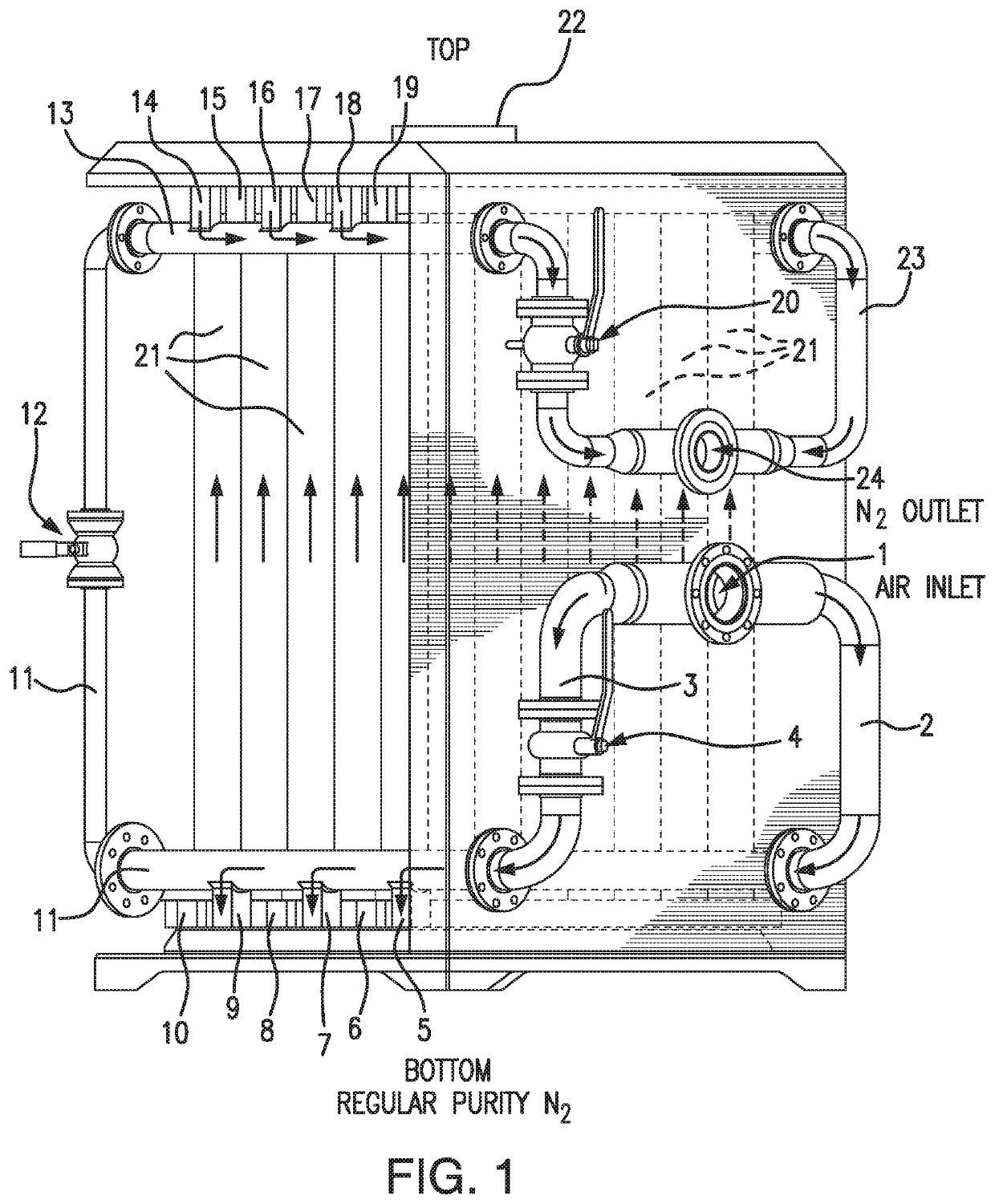
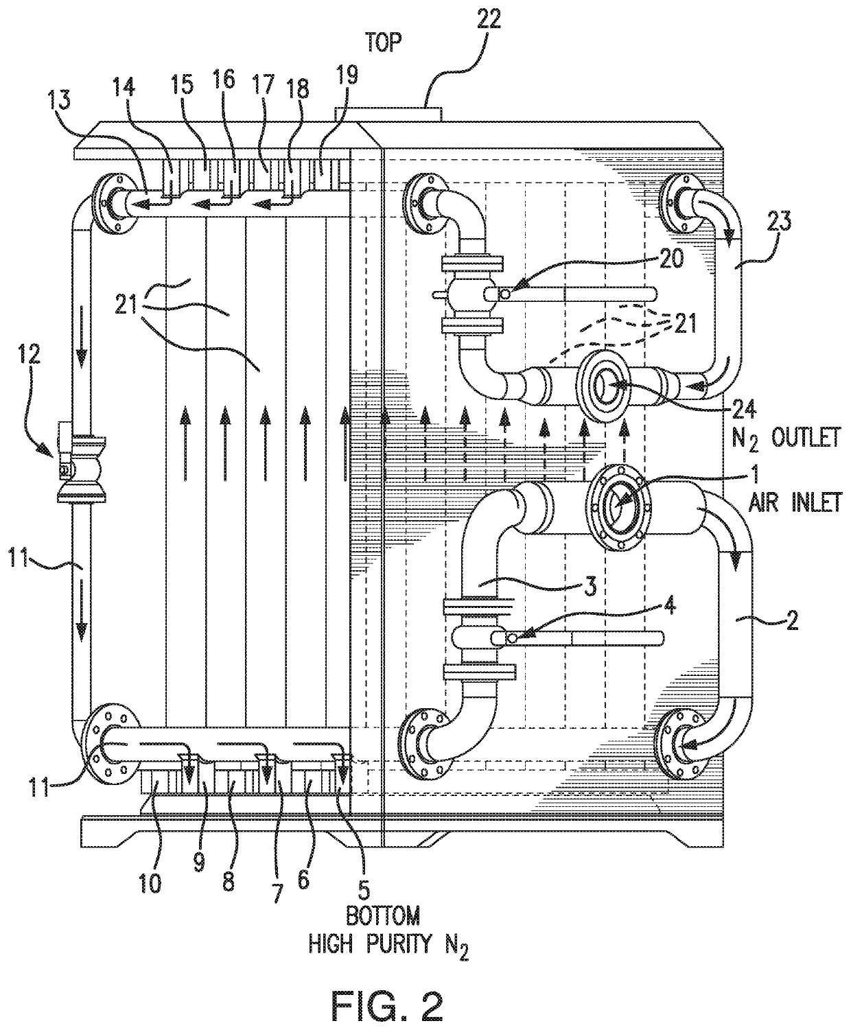
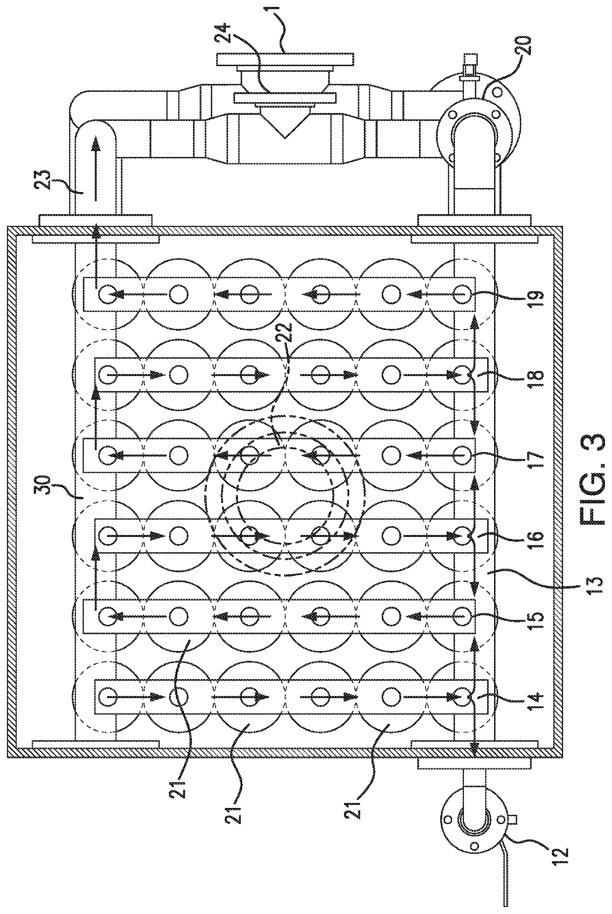
[0041]The present invention comprises an apparatus having a plurality of membrane modules, wherein the apparatus has a first configuration in which the modules are all operated in parallel, and a second configuration in which the modules comprise two groups which are effectively arranged in series. The configuration of the apparatus can be changed simply by changing the position of a small number of valves, typically three valves.

[0042]The parallel configuration is used to produce a gas having moderate purity, and the series configuration is used to produce a gas having high purity.

[0043]In brief, when the system is operated in the parallel mode, the feed gas is distributed among all of the modules, and passes through the modules simultaneously. When the system is operated in the series mode, the feed gas is directed into some, but not all, of the modules, and the product of said modules is then directed into some or all of the remaining modules, i.e. those modules that did not rece...


PUM


Abstract

A device for separating a gas, such as air, into components, includes a plurality of modules, each module having one or more polymeric membranes capable of gas separation. A set of valves, pipes, and manifolds together arrange the modules in one of two possible configurations. In a first configuration, the modules are arranged in parallel. In a second configuration, the modules are divided into two groups which are arranged in series. The device can be switched from parallel to series, or from series to parallel, simply by changing the positions of a small number of valves, typically three valves. The device can therefore produce gas either of higher purity, or moderate purity, depending on the settings of the valves. The device also includes improved structures for connecting the modules to inlet and outlet manifolds, and also includes devices for temporarily isolating one or more modules from the system.

Description

CROSS-REFERENCE TO RELATED APPLICATION[0001]This is a continuation-in-part of U.S. patent application Ser. No. 16 / 158,626, filed Oct. 12, 2018, which claims the priority of U.S. provisional patent application Ser. No. 62 / 586,308, filed Nov. 15, 2017. The entire disclosures of the above-cited applications are hereby incorporated by reference.BACKGROUND OF THE INVENTION[0002]The present invention relates to the separation of gas into components using polymeric membranes.[0003]It has been known to use a polymeric membrane to separate air into components. Various polymers have the property that they allow different gases to flow through, or permeate, the membrane, at different rates. A polymer used in air separation, for example, will pass oxygen and nitrogen at different rates. The gas that preferentially flows through the membrane wall is called the “permeate” gas, and the gas that tends not to flow through the membrane is called the “non-permeate” or “retentate” gas. The selectivity ...

Claims


Application Information

Patent Timeline
Patent Type & Authority Applications(United States)
IPC IPC(8): B01D53/22B01D63/06
CPCB01D53/226B01D53/227B01D63/06B01D2313/18B01D2313/105B01D2313/125B01D2053/221B01D63/04B01D2256/10B01D2256/12B01D2053/224
Inventor REESE, STEVENSTRAUB, MARCJENSVOLD, JOHN A.KOCIOLEK, ROBERT
Owner GENERON IGS
Why Eureka
Try Eureka