Cleaner

a technology of cleaning machine and cleaning brush, which is applied in the field of cleaning brush, can solve the problems of difficult effective mopping of the floor, difficult to effectively mop the floor, and inability to inhale foreign materials on the floor, etc., and achieves the effects of wide cleaning range, large width, and easy disposal

Pending Publication Date: 2021-02-04
LG ELECTRONICS INC
View PDF9 Cites 1 Cited by
  • Summary
  • Abstract
  • Description
  • Claims
  • Application Information

AI Technical Summary

Benefits of technology

[0055]Tenthly, according to the present disclosure, since a storage opening surface is disposed at an upper side of a partition, a movement of a collected foreign material back to the collection space again can be minimized.
[0056]Eleventhly, according to the present disclosure, a foreign material in a storage space can be easily discarded by separating a sweep module and thereafter separating a dust housing since the dust housing is disposed at a front side of a housing assembly.
[0057]Twelfthly, according to the present disclosure, a body has a circular shape and a dry-type module does not protrude to an outside of the body. Accordingly, the cleaner can be freely rotated at any position in a cleaning area. Also, an agitator can have a sufficiently large width, and thus, a cleaning range can be wide. Further, a mopping operation while collecting a foreign material having a relatively large size can be performed.

Problems solved by technology

1, both of wet-type cleaning and traveling are performed through the pair of cleaners, but inhaling of a foreign material on a floor is impossible.
However, in KR'112, since a wheel and a motor for traveling or driving of the robot cleaner and a suction fan and a motor for inhaling a dust should be separately provided, an operation structure may be complex.
Further, in the conventional art, since a robot cleaner proceeds only by friction force of spin mops and a water level of stored water in a water tank is variable, it may be difficult to effectively mop a floor and driving power may be not sufficient.
Particularly, it may be very difficult for the conventional wet-type robot to adjust a traveling direction by friction force with rotating mops.
Accordingly, cleaning is performed only by a random driving, and cleaning by a pattern driving being able to meticulously clean is impossible.
Further, in the conventional art, since the cleaning is possible only by the random driving, meticulous cleaning at a corner of a floor or an area adjacent to a wall may be difficult.

Method used


Image

  • Cleaner
  • Cleaner
  • Cleaner

Examples


Embodiment Construction

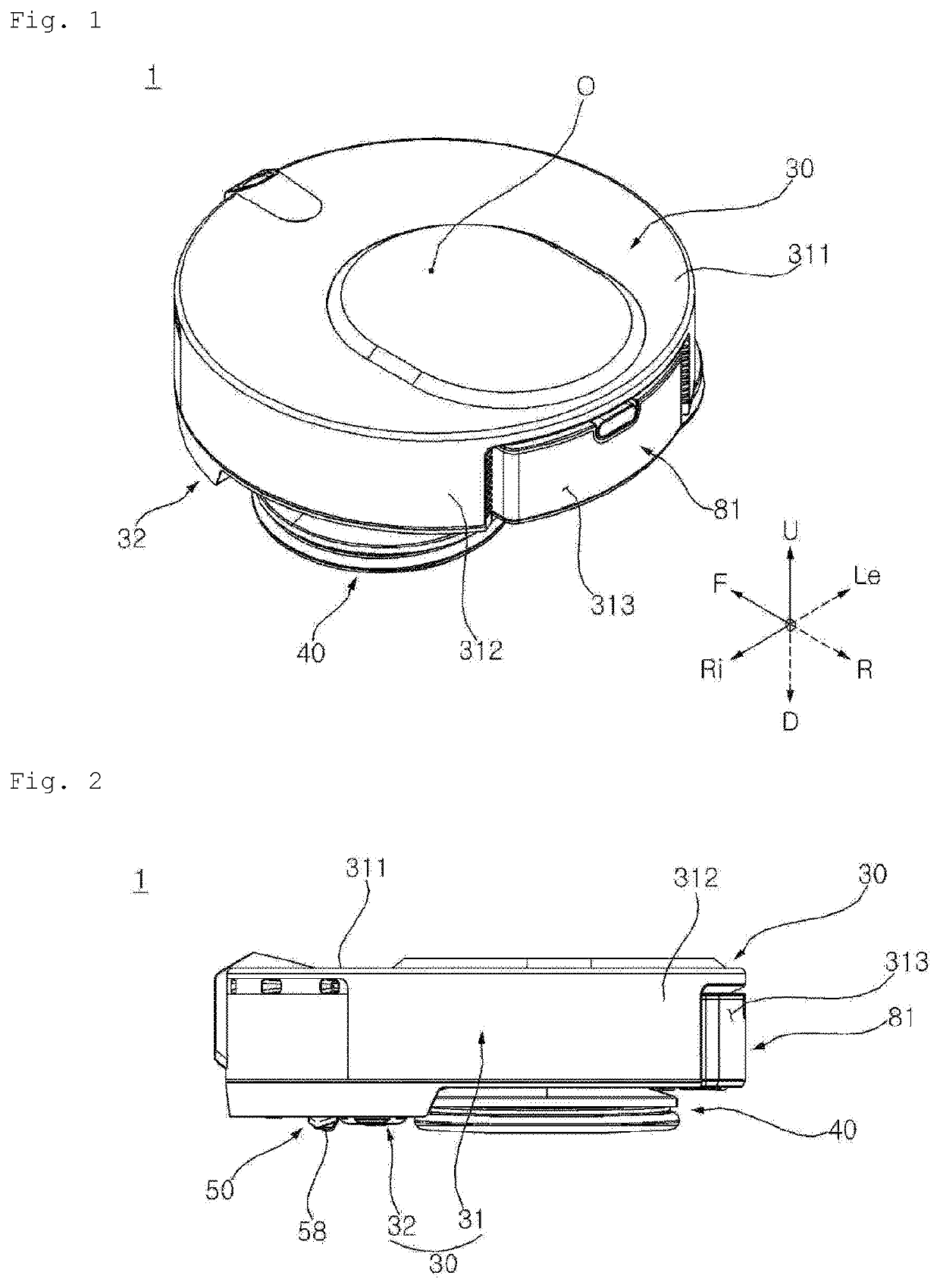
[0083]Expressions referring to directions such as a front direction (a frontward direction or a forward direction) (F), a rear direction (a rearward direction) (R), a left direction (a leftward direction) (Le), a right direction (a rightward direction) (Ri), an upper direction (an up direction or an upward direction) (U), and a down direction (an downward direction) (D), or so on may be defined base on a driving direction of a cleaner (a vacuum cleaner). This is just for explaining the present disclosure with reference to the accompanying drawings to be clearly understood. Therefore, directions may be defined differently depending on where a reference is placed.

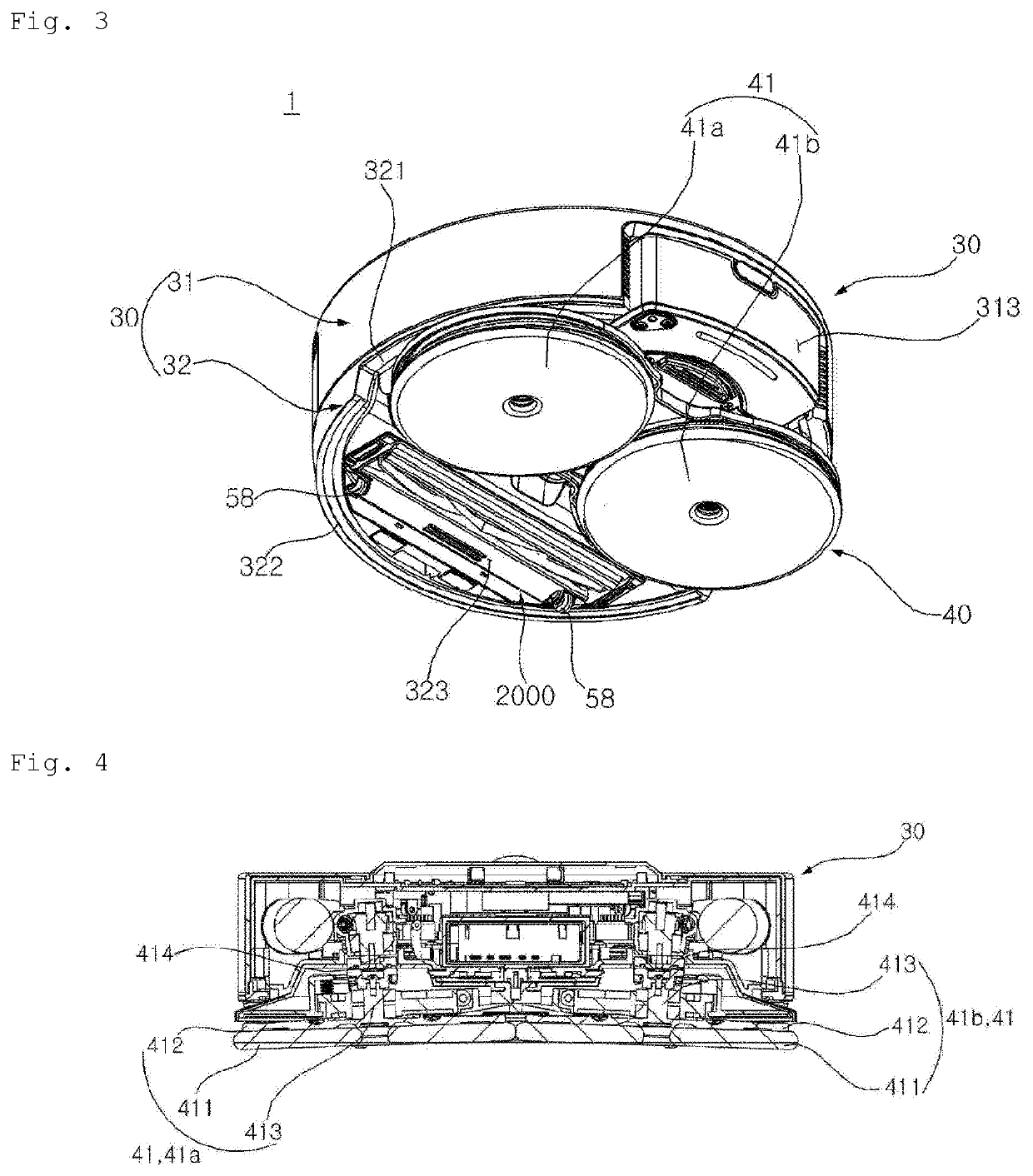
[0084]For example, a direction parallel to an imaginary line connecting a central axis of a left spin mop and a central axis of a right spin mop may be defined as a left-right direction. A direction perpendicular to the left-right direction and parallel to the central axes of the spin mops or has an error angle within 5 degre...


PUM


Abstract

A mobile cleaner includes a body and a sweep module. The body has an installation space within the body and an insertion opening exposed to the underside of the body. The sweep module is detachably assembled to the installation space through the insertion hole. The sweep module includes a dust housing and an agitator. The dust housing includes a collection space for collecting the foreign material from the surface and a storage space where the foreign material is stored. The agitator is rotatably assembled to the dust housing and is configured to direct the foreign material from the surface to the collection space.

Description

BACKGROUND1. Field[0001]The present disclosure relates to a cleaner for mopping or wiping a floor, and to a cleaner capable of maximizing a cleaning area by an agitator in a structure in which the agitator and a dust housing are integrated with each other.2. Description[0002]A cleaner is a device that cleans a floor by inhaling a foreign material such as a dust on the floor or wiping a foreign material on the floor. Recently, a cleaner capable of mopping a floor has been developed. In addition, a robot cleaner is a device that cleans while driving or traveling on its own.[0003]In Korean Patent Publication No. 10-1602790 (hereinafter, referred to as KR'790), a robot cleaner capable of traveling while performing wet-type cleaning using a wet-type cleaner is disclosed.[0004]In KR'790, the robot cleaner includes a pair of cleaners arranged in a left-right direction, and a driving unit that rotates each cleaner by providing driving force.[0005]However, in KR'790, the robot cleaner includ...

Claims


Application Information

Patent Timeline
Patent Type & Authority Applications(United States)
IPC IPC(8): A47L11/283A47L11/24A47L11/40
CPCA47L11/283A47L11/24A47L11/4038A47L11/4041A47L11/4013A47L11/4061A47L2201/00A47L11/161A47L11/4066A47L11/18A47L11/2025A47L11/4083A47L11/4016
Inventor JANG, JAEWONKIM, YOUNGBIN
Owner LG ELECTRONICS INC
Why Eureka
Try Eureka