
Anchored implant for a nasal prosthesis

a technology for anchoring implants and prostheses, which is applied in the field of nasal prostheses, can solve the problems of affecting the patient's daily hygiene, the psychological impact of a missing external nose is devastating, and the patient is invariably a recluse, so as to prevent the pivot or rotational motion of the nasal prosthesis, the effect of encouraging regular hygien

Active Publication Date: 2021-02-11
TMJ ORTHOPAEDICS PTY LTD
View PDF0 Cites 0 Cited by
  • Summary
  • Abstract
  • Description
  • Claims
  • Application Information

AI Technical Summary

Benefits of technology

The design of the nasal prosthesis prevents it from pivting or rotating, and it is securely held in place by three fixation points. This makes it easy for patients to clean the metal framework and maintain good hygiene.

Problems solved by technology

In rare cases, the external nose may be missing due to trauma or following surgical resection for cancer or other destructive pathology.
A missing external nose, which may include the nasal bridge, nasal dorsum and tip together with the alar and columella which surround the nasal apertures, results in a hideous deformity on the face which attracts negative reactions by others.
The psychological impact of a missing external nose is devastating for the patient who invariably becomes a recluse.
While there are various surgical reconstructive procedures available to rebuild a missing external nose, often utilizing skin from the patient's forehead, the results are usually unpredictable and the natural aesthetics are difficult to recreate accurately.
Alternatively, prosthetic noses have been devised over the centuries that have had less than favourable outcomes because of the lack of suitable anchorage points around the nasal defect.
Specifically, the bone surrounding the nasal aperture is very seven and, as such, conventional osseointegrated implants have had limited success.

Method used


Image

  • Anchored implant for a nasal prosthesis
  • Anchored implant for a nasal prosthesis

Examples


Embodiment Construction

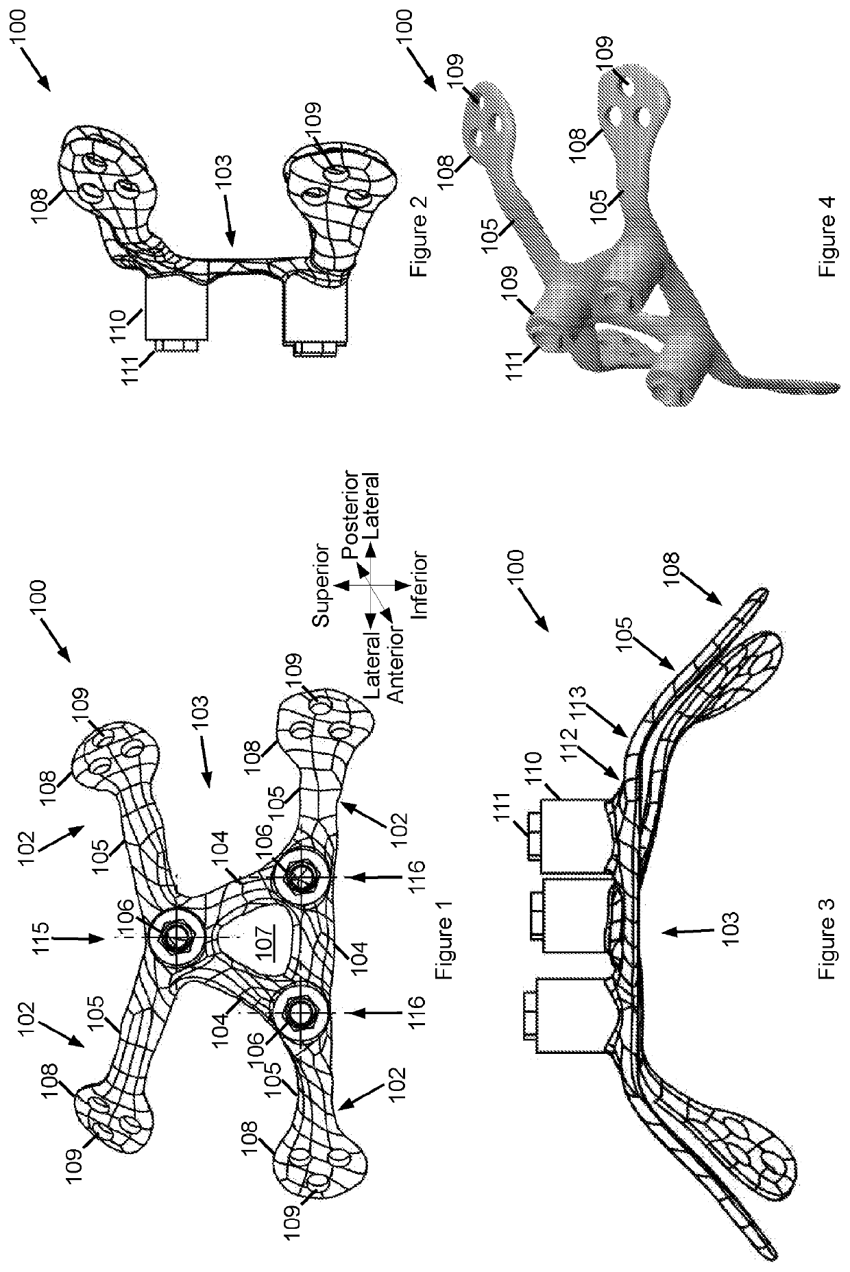
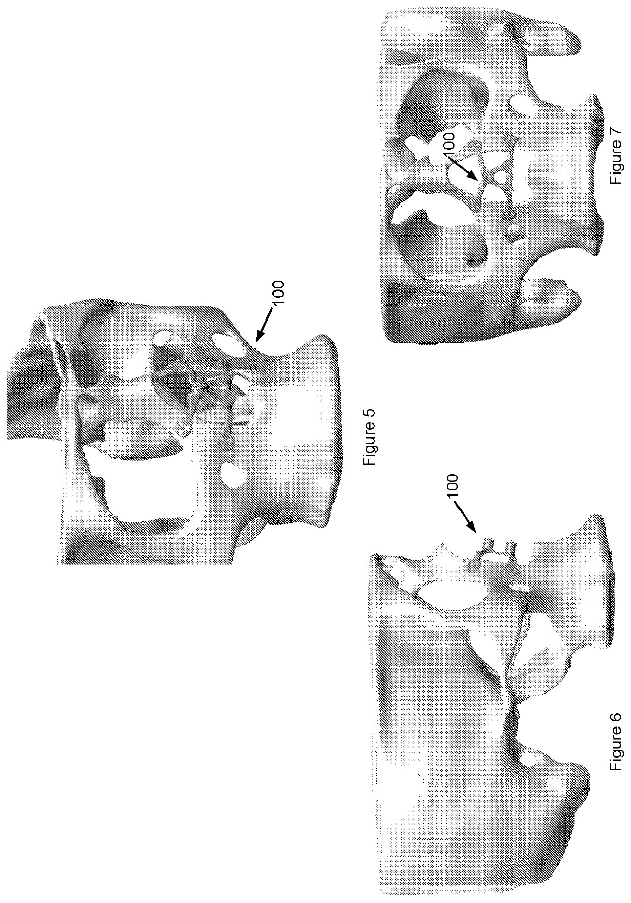
[0041]FIG. 1 shows a top view of an anchored implant 100 for a nasal prosthesis in an embodiment which, for orientational convenience, will be described with reference to the orientational axes provided in FIG. 1 defining top / superior, bottom / inferior, side / lateral, front / anterior and rear / posterior reference points.

[0042]The implant 100 may be integrally formed of biocompatible material such as titanium.

[0043]The implant 100 comprises a central section 103 supporting at least three nasal prosthesis fixation points 106. In a preferred embodiment, the implant 100 has three nasal prosthesis fixation points 106 at a respective superior vertex 115 and two inferior lateral vertices 116.

[0044]Once the implant 100 is anchored, a nasal prosthesis (not shown) is affixed to the implant 100 at the fixation points 106.

[0045]In the preferred embodiment shown, the central section 103 is substantially triangular, thereby minimising cross-sectional area between the fixation points 106, thereby maxi...


PUM


Abstract

There is provided herein a bone anchored implant that is used to support a nasal prosthesis in patients with a missing external nose. The implant consists of central section (which is preferably generally triangular) suspended within the aperture of the nasal cavity by four fixation arms which extend radially to engage the surrounding maxillary bone. The triangular portion may support three fixation points, one at each corner of the triangular portion, which in turn, directly engage the nasal prosthesis either via magnets or mechanical locking interface. Extending radially from the triangular section, the four fixation arms may flatten to a clover leaf arrangement of three apertures which accommodate micro-screws that secure the implant to the surrounding maxillary bone.

Description

FIELD OF THE INVENTION[0001]This invention relates generally to nasal prostheses and, more particularly, this invention relates to an anchored implant for a nasal prosthesis.BACKGROUND OF THE INVENTION[0002]The human nose occupies the central part of the face and is an essential appendage that provides the important function of smell and filters and humidifies the air we breathe. The nose also plays a central role in the aesthetics of the face. The nose can also support spectacles such as sunglasses or eyeglasses for the visually impaired.[0003]In rare cases, the external nose may be missing due to trauma or following surgical resection for cancer or other destructive pathology. A missing external nose, which may include the nasal bridge, nasal dorsum and tip together with the alar and columella which surround the nasal apertures, results in a hideous deformity on the face which attracts negative reactions by others. The psychological impact of a missing external nose is devastating...

Claims


Application Information

Patent Timeline
IPC IPC(8): A61F2/18A61F2/00A61F2/28
CPCA61F2/186A61F2/0059A61F2/2875A61F2230/0023A61F2210/009A61F2220/0041A61F2002/2885A61B17/24A61B2017/00792A61F2/78A61F2/18
Inventor DIMITROULIS, GEORGE
Owner TMJ ORTHOPAEDICS PTY LTD
Learn More